
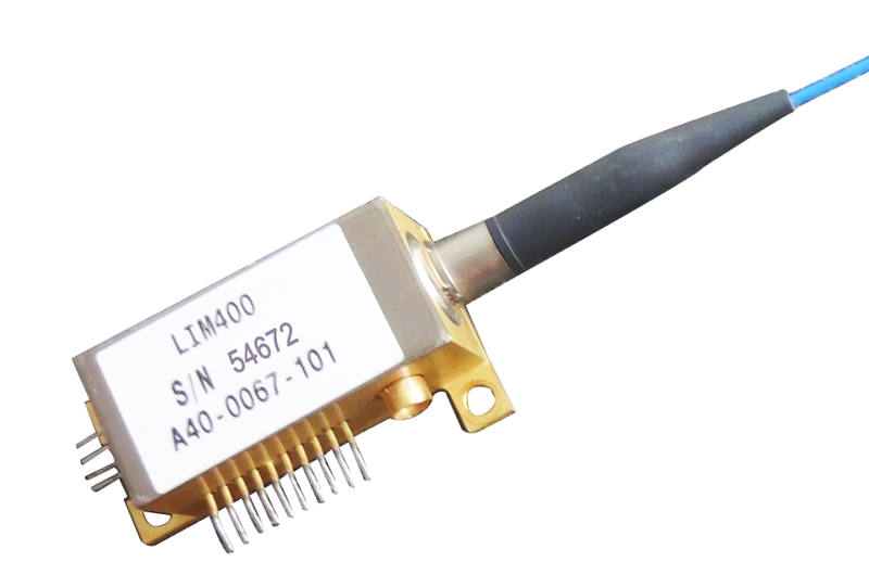

Directly modulated laser 40G EML Cyoptics LIM400 Electro-absorption Modulated Laser
The CyOptics (formerly Apogee Photonics, now Broadcom Limited) LIM400 Laser-Integrated Module is a compact, high-performance device used in 40Gb/s long-reach data transmission. The LIM400 enables ITU and MSA compliance with a dispersion penalty of less than 1dB over 40ps/nm of fiber, and an end-of-life output power-exceeding 0dBm. The LIM400 is ideal for both 2km VSR and 80km LR dispersion-compensated applications CyOptics’ innovation has led to the reduction of size and power requirements, enabling MSA-compliant transponders and increased board densities. The LIM400 integrates both laser and modulator into a single package, thereby eliminating a separate TEC. A proprietary internal-biasing technology permits direct connection to the RF port of the EAM, eliminating the need for an external bias-tee. Lastly, the low-profile corner-mount design of the LIM400 allows additional board space savings.
 Save to Favorites
Overview
Specifications
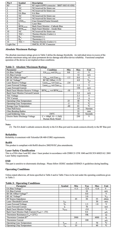
| Parameter | Value |
|---|---|
| Table2 Absolute Maximum — EA Bias Voltage | min:0.0 V;max:+5 V |
| Absolute Maximum — EA Bias Current [Damage/stress limit only;functional compliant operation not implied] | max:14 mA |
| Table2 Absolute Maximum — RF DC Offset Voltage | min:-1.5 V;max:0.0 V |
| Table2 Absolute Maximum — RF AC Voltage | max:4.0 Vpp |
| Absolute Maximum — Laser Reverse Voltage [Damage/stress limit only;functional compliant operation not implied / Laseranode with respect to CaseRtn] | min:-2.0 V |
| Absolute Maximum — Laser Forward Voltage [Damage/stress limit only;functional compliant operation not implied / Laseranode with respect to CaseRtn] | max:1.8 V |
| Absolute Maximum — Laser Forward Current [Damage/stress limit only;functional compliant operation not implied] | max:150 mA |
| Absolute Maximum — Back Facet Monitor Reverse Voltage [Damage/stress limit only;functional compliant operation not implied / BFManode with respect to BFMcathode] | min:-10 V |
| Absolute Maximum — Back Facet Monitor Forward Current [Damage/stress limit only;functional compliant operation not implied] | max:5.0 mA |
| Absolute Maximum — TEC Voltage [Damage/stress limit only;functional compliant operation not implied] | max:3.5 V |
| Absolute Maximum — TEC Current [Damage/stress limit only;functional compliant operation not implied] | max:1.6 A |
| Absolute Maximum — Operating Chip Temperature [Damage/stress limit only;functional compliant operation not implied] | min:25 °C;max:40 °C |
| Absolute Maximum — Operating Case Temperature [Damage/stress limit only;functional compliant operation not implied] | min:-5 °C;max:75 °C |
| Absolute Maximum — Storage Case Temperature [Damage/stress limit only;functional compliant operation not implied] | min:-40 °C;max:85 °C |
| Absolute Maximum — Fiber Pull Force [Damage/stress limit only;functional compliant operation not implied] | max:10 Newton |
| Absolute Maximum — Fiber Bending Radius [Damage/stress limit only;functional compliant operation not implied] | max:25 mm |
| Absolute Maximum — Lead Soldering Time [Damage/stress limit only;functional compliant operation not implied / 250°C] | max:10 Seconds |
| Absolute Maximum — Electrostatic Discharge Voltage [Damage/stress limit only;functional compliant operation not implied / C=100pF,R=1.5kΩ;Human Body Model] | max:250 V |
| Table3 Operating Conditions — EA Bias Voltage | min:+1.5 V;typical:+2.0 V;max:+3.0 V |
| Operating Conditions — EA Bias Current [Normal operating condition;Table4 BOL and Table5 EOL requirements must meet Table3 unless otherwise stated] | typical:10 mA |
| Table3 Operating Conditions — RF AC Voltage | typical:3.0 Vpp |
| Operating Conditions — RF Source Impedance [Normal operating condition;Table4 BOL and Table5 EOL requirements must meet Table3 unless otherwise stated] | min:45 ohms;typical:50 ohms;max:55 ohms |
| Operating Conditions — Laser Threshold Current ITH [Normal operating condition;Table4 BOL and Table5 EOL requirements must meet Table3 unless otherwise stated] | max:30 mA |
| Operating Conditions — Laser Forward Voltage VF [Normal operating condition;Table4 BOL and Table5 EOL requirements must meet Table3 unless otherwise stated] | typical:1.3 V;max:1.8 V |
| Operating Conditions — Laser Forward Current IF [Normal operating condition;Table4 BOL and Table5 EOL requirements must meet Table3 unless otherwise stated] | typical:70 mA |
| Operating Conditions — Back Facet Monitor Voltage VBFM [Normal operating condition;Table4 BOL and Table5 EOL requirements must meet Table3 unless otherwise stated] | typical:-5.0 V |
| Operating Conditions — Back Facet Monitor Dark Current [Normal operating condition;Table4 BOL and Table5 EOL requirements must meet Table3 unless otherwise stated / VBD=-5V] | typical:0.4 µA |
| Operating Conditions — Thermistor Resistance [Normal operating condition;Table4 BOL and Table5 EOL requirements must meet Table3 unless otherwise stated / Top=+25°C;literal10k in Ω unit row] | typical:10k |
| Operating Conditions — Thermistor Constant B [Normal operating condition;Table4 BOL and Table5 EOL requirements must meet Table3 unless otherwise stated / Actual named constant;definition equation not converted into extra metrics] | min:3900 K;max:4000 K |
| Operating Conditions — Thermistor Current [Normal operating condition;Table4 BOL and Table5 EOL requirements must meet Table3 unless otherwise stated] | typical:100 µA |
| Operating Conditions — Operating Case Temperature Tcase [Normal operating condition;Table4 BOL and Table5 EOL requirements must meet Table3 unless otherwise stated] | min:-5 °C;max:70 °C |
| Operating Conditions — Operating Chip Temperature Top [Normal operating condition;Table4 BOL and Table5 EOL requirements must meet Table3 unless otherwise stated] | typical:35 °C;max:40 °C |
| BOL — Output Wavelength λ [Beginning of Life;under Table3 normal operating conditions as recorded separately / DFB output wavelength at operating temperature35–40°C;LIM400 available on specified operating wavelength] | min:1530 nm;typical:1550 nm;max:1563 nm |
| BOL — Mean Modulated Output Power Pout [Beginning of Life;under Table3 normal operating conditions as recorded separately] | min:1.0 dBm |
| BOL — Dynamic Extinction Ratio ER [Beginning of Life;under Table3 normal operating conditions as recorded separately / Tchip=Top at operation;PSPL5881/5882 RF-driver cascade,3Vpp RF input,NRZ40Gb/s multiplexed from four parallel10Gb/s PRBS2³¹−1 channels] | min:9.5 dB |
| BOL — Dispersion Penalty DP [Beginning of Life;under Table3 normal operating conditions as recorded separately / Actual row40Gbps Dispersion40ps/nm;Note5 instead specifiesNRZ10Gb/s,40km680ps/nm;test applicability conflict unresolved] | max:1.0 dB |
| BOL — Optical Return Loss [Beginning of Life;under Table3 normal operating conditions as recorded separately] | min:27 dB |
| BOL — Spectral Width [Beginning of Life;under Table3 normal operating conditions as recorded separately / DFB CW,+4dBm optical unmodulated output,EA diode bias0.00V;FWHM bandwidth] | max:10 MHz |
| BOL — Relative Intensity Noise RIN [Beginning of Life;under Table3 normal operating conditions as recorded separately / 1MHz to10GHz] | max:-140 dB/Hz |
| BOL — Side-Mode Suppression Ratio SMSR [Beginning of Life;under Table3 normal operating conditions as recorded separately] | min:35 dB |
| BOL — E/O3dB Bandwidth S21BW [Beginning of Life;under Table3 normal operating conditions as recorded separately / S21 andS11 measured at Top=35°C] | min:27 GHz;typical:30 GHz |
| BOL — E/O Transfer Ripple [Beginning of Life;under Table3 normal operating conditions as recorded separately / DC to20GHz] | max:2.5 dBpp |
| BOL — RF Return Loss S11 [Beginning of Life;under Table3 normal operating conditions as recorded separately / 100kHz to10GHz / S21 andS11 measured at Top=35°C] | min:15 dB;typical:23 dB |
| BOL — RF Return Loss S11 [Beginning of Life;under Table3 normal operating conditions as recorded separately / 10GHz to20GHz / S21 andS11 measured at Top=35°C] | min:5 dB;typical:8 dB |
| BOL — RF Return Loss S11 [Beginning of Life;under Table3 normal operating conditions as recorded separately / 20GHz to30GHz / S21 andS11 measured at Top=35°C] | min:2 dB;typical:3.5 dB |
| BOL — RF Return Loss S11 [Beginning of Life;under Table3 normal operating conditions as recorded separately / 30GHz to40GHz / S21 andS11 measured at Top=35°C] | min:1.5 dB;typical:2.5 dB |
| BOL — Back Facet Monitor Operating Current IBFM [Beginning of Life;under Table3 normal operating conditions as recorded separately] | min:100 µA;max:1000 µA |
| BOL — Thermistor Resistance Rth [Beginning of Life;under Table3 normal operating conditions as recorded separately / Top=25°C] | min:9.5 KΩ;max:10.5 KΩ |
| BOL — TEC Voltage [Beginning of Life;under Table3 normal operating conditions as recorded separately] | max:2.0 V |
| BOL — TEC Current [Beginning of Life;under Table3 normal operating conditions as recorded separately] | max:1.0 A |
| BOL — TEC Power Consumption [Beginning of Life;under Table3 normal operating conditions as recorded separately / Top=35°C to40°C] | max:1.5 Watts |
| EOL — Change in RF Extinction Ratio ΔER [End of Life change criterion;under Table3 normal operating conditions unless otherwise stated / Lifetime] | max:0.5 dB |
| EOL — Mean Modulated Output Power change ΔPout [End of Life change criterion;under Table3 normal operating conditions unless otherwise stated / Lifetime and Temperature;actualΔPout change,not absolute optical power] | max:1.0 dB |
| EOL — Change in Laser Forward Current ΔIlaser [End of Life change criterion;under Table3 normal operating conditions unless otherwise stated / Lifetime] | max:25 % |
| EOL — Change of Thermistor Resistance ΔRth [End of Life change criterion;under Table3 normal operating conditions unless otherwise stated / Tth=25°C;actual single Maximum+5%,not invented±5%] | max:+5 % |
| EOL — Change of TEC Power Consumption ΔPTEC [End of Life change criterion;under Table3 normal operating conditions unless otherwise stated / Lifetime] | max:5 % |
| Pigtail/Optical Connector — Fiber type [Corning fiber type or equivalent] | SMF28 900µm tight buffer |
| Pigtail/Optical Connector — Fiber Jacket Color | Blue |
| Pigtail/Optical Connector — Optical Connector [Literal source connector options;full ordering-model assignment not provided] | FC/,SC/,LC/UPC |
| Pigtail/Optical Connector — Optical Connector Return Loss | min:55 dB |
| Pigtail/Optical Connector — Pigtail length | min:0.9 m;max:1.1 m |
| Pigtail/Optical Connector — Mode field diameter | min:8.5 µm;max:10.5 µm |
| Pigtail/Optical Connector — Cladding diameter | min:122 µm;max:128 µm |
| Pigtail/Optical Connector — Outer jacket diameter [Tight buffer] | min:.8 mm;max:1.0 mm |
| Pigtail/Optical Connector — Minimum Bend Radius [Loss<0.1dB for1coil] | min:25 mm |
| RF Input Connector [Actual named RF connector component,not product model] | GPPO — B007-M43-01-030 |
| Light Out — Fiber and Connector [Actual LightOut pin-table description;Table6 lists other connector options,exact ordering variant association not supplied] | SMF28,FC/PC Connector |
Applications
Key Features
Datasheet
Please provide your email to download the datasheet.
Invalid email format. Please try again.
Supplier Information
Related Products
-
 100W Subnanosecond Infrared Laser
Laser Modules & Systems
Guoshunlaser
M² Beam quality: <1.6 Average Output Power: >100 Power adjustment Range: 0~100 %
-
 100W Picosecond Green Fiber Laser
Laser Modules & Systems
Guoshunlaser
M² Beam quality: <1.3 Average Output Power: >100 Power adjustment Range: 0~100 %
-
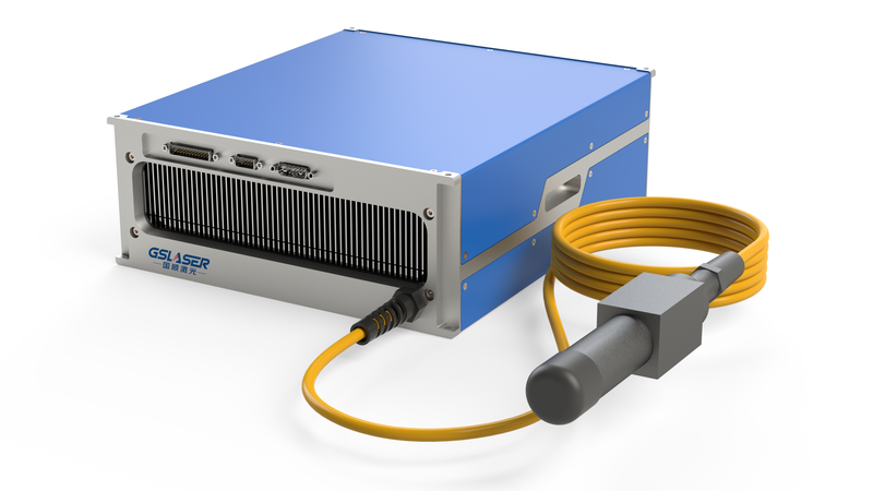 100W Nanosecond Infrared Fiber Laser
Laser Modules & Systems
Guoshunlaser
M² Beam quality: <1.4 Average Output Power: >100 Power adjustment Range: 0~100 %
-
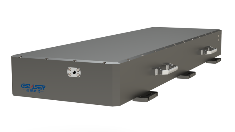 100W Femtosecond Infrared Laser
Laser Modules & Systems
Guoshunlaser
M² Beam quality: <1.3 Average Output Power: >100 Power adjustment Range: 0~100 %
-
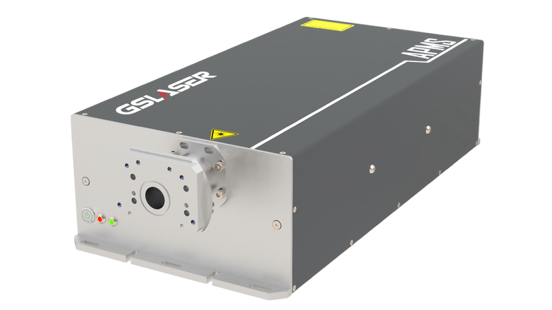 10W Compact Picosecond Infrared Laser
Laser Modules & Systems
Guoshunlaser
M² Beam quality: <1.2 Average Output Power: >10 Power adjustment Range: 0~100 %
Related Articles
As a core precision optical component for wavelength screening, frequency locking and spectral demodulation, optical etalons are widely used in high-end scientific research and precision laser equipment.
As a vital emerging sector of modern three-dimensional spatial economy, the low-altitude economy has become a new global growth driver. It covers a wide range of commercial scenarios, including UAV navigation and obstacle avoidance, precise airspace management, aerial mapping, low-altitude logistics distribution, security monitoring and emergency disaster rescue. Nevertheless, frequent extreme weather, complex terrain obstacles and increasingly dense low-altitude flight activities pose severe challenges to the safety and stability of low-altitude aircraft operations.
Laser pump sources are the core energy input component of solid-state lasers and laser amplifiers, and their performance directly determines the output power, beam quality and service life of the entire laser system. In scenarios such as industrial processing, scientific research experiments and high-end equipment, improper pump source selection will not only result in substandard system performance, but also bring a series of problems such as rapid device degradation and high operation and maintenance costs. This article sorts out the core selection logic and key pitfalls of pump source procurement, and provides selection references based on mature, mass-produced high-reliability products to help purchasers efficiently screen suitable products.
Shandong Haucore Optoelectronics Co., Ltd. introduces the HGLD‑792‑COS‑D‑10WB semiconductor laser within its COS series. Delivering an output power of 10 W at a central wavelength of 792 nm, this device adopts gold‑tin bonding COS packaging. Featuring high reliability and long service life, it serves as a preferred pump source for solid‑state lasers and is widely deployed in industrial processing, laser display, medical & aesthetic treatment, scientific research and other fields.
Loading...
Name
Phone
Organization
Use Case

Database Platform