What Is a 3dB Hybrid Coupler? Working Principle & Key Applications of UMCC HC-W030-MN
Published: 2026-08-05 15:00:24 Views: 46
1. Why Choose 3dB Hybrid Couplers
For low-frequency RF, electromagnetic testing and power combining systems, conventional resistive power dividers bring high insertion loss, while standard directional couplers cannot provide equal-amplitude signals with 180° phase shift. They fail differential circuits, balanced amplifiers and signal cancellation systems.
A 3dB 180° hybrid coupler is a passive microwave component designed to equally split or combine RF signals with 0° and 180° phase difference on two output paths. It features high port isolation and low loss, solving core challenges of power distribution, noise suppression and balanced testing for low-frequency RF systems.
UMCC HC-W030-MN is a commercial-grade standard 3dB hybrid coupler covering 0.03–10 MHz. It delivers low insertion loss, high isolation and wide temperature resistance, making it the ideal component for industrial RF, EMC testing and RF power circuits.
2. Working Principle of 3dB Hybrid Coupler
HC-W030-MN is a 180° / 3dB hybrid bridge with a standard 4-port layout: IN1 (0° input), IN2 (180° input), and two output ports. It operates in two core modes: power splitting and power combining.
- Power Splitting Mode: RF signal fed into one input port is evenly divided into two paths, each output attenuated by 3dB with 180° phase offset between the two outputs.
- Power Combining Mode: Two equal-amplitude signals injected into IN1 and IN2 can be summed or canceled via the 180° phase difference, widely used for noise reduction and balanced power amplification.
- Port Isolation Design: Special internal transmission line topology minimizes signal leakage between input ports and output ports, eliminating cross-talk and stabilizing system performance.
The unit features a standard 50 Ohm nominal impedance with N female connectors for compatibility with general RF cables and test instruments.
3. Core Product Highlights of UMCC HC-W030-MN
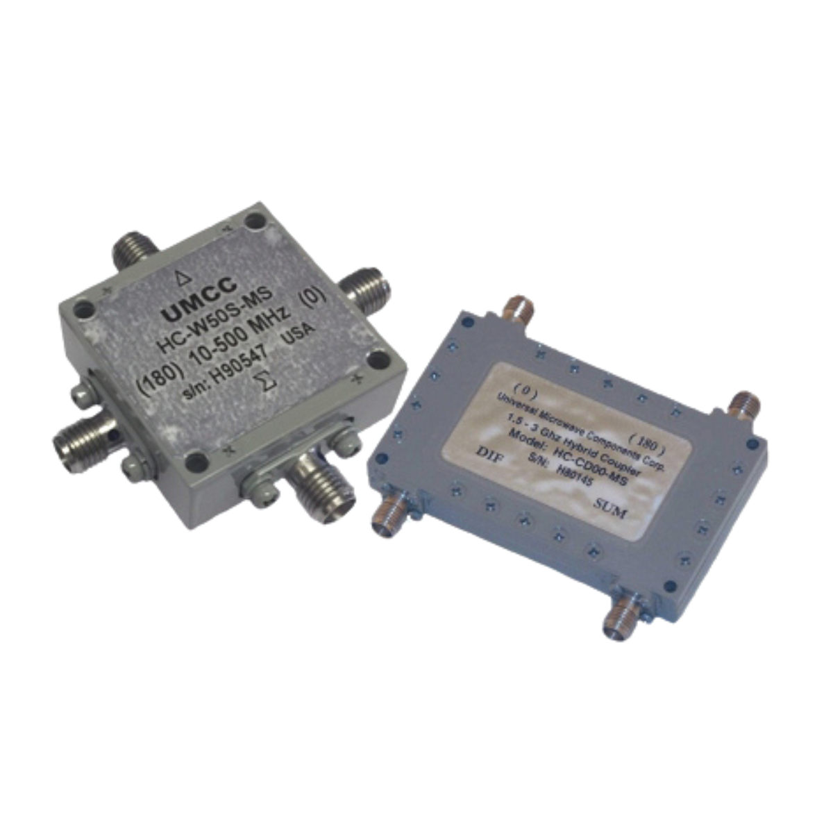
- Ultra-low frequency coverage: 0.03–10 MHz full band, suitable for low-frequency RF, EMC and power-frequency RF testing;
- Ultra-low insertion loss: Max insertion loss limited to 0.5 dB for minimal signal power loss;
- Superior amplitude balance & isolation: Amplitude balance ≤0.3 dB, port isolation ≥25 dB for uniform signal division and low cross-talk;
- High power handling: 8W CW / peak power rating for continuous operation in medium-low power RF circuits;
- Excellent impedance matching: Max VSWR 1.30:1 across full band, eliminating signal reflection distortion;
- Rugged environmental performance: Operating temperature -40 ℃ ~ +85 ℃, storage -50 ℃ ~ +100 ℃; compliant with MIL-STD-202F standards for humidity, shock, vibration, thermal shock and high altitude testing;
- Standard N(f) connector housing: Four N female ports, robust metal chassis with standardized mounting holes for easy equipment integration.
4. Key Product Applications
- Balanced RF Amplifier Circuits: Power combining for dual power amplifiers, even-order harmonic suppression and system noise reduction;
- EMC Electromagnetic Compatibility Testing: Low-frequency conducted interference measurement, differential RF signal capture, common-mode noise suppression;
- RF Signal Combining & Cancellation Systems: Signal nulling, interference simulation, differential signal generator auxiliary modules;
- Industrial Low-Frequency RF Equipment: Power splitting for wireless monitoring & low-frequency RF transceiver modules;
- Laboratory RF Metrology Instruments: Dual-channel signal division, phase difference testing, multi-channel RF source expansion;
- Military & Vehicle RF Subsystems: Vibration and temperature resistant low-frequency RF power split components.