

Dual-Channel High-Power RF Driver MQH0XX-YYDM-ZZZ-2S
The MQH0XX-YYDM-ZZZ-2S is a dual-channel high-power RF driver covering24–110 MHz, providing dual-channel RF output up to100 W into50 Ω with analog and digital modulation. Designed for acousto-optic Q-switches, it provides stable, reliable drive for high-power pulsed lasers. Two digital inputs support fixed-width and variable-width modes. Analog input adjusts RF power. ZZZ selects A05 (standard analog control), R05 (analog control switched to full RF output), FPS (first-pulse suppression), or PPK (prepulse elimination). Frequency XX, power YY, and control mode ZZZ are factory configured to order. Forced-air cooling supports continuous high-power operation and long-term reliability. Fixed-width pulses are set by an adjustable internal circuit; variable-width pulses follow the external input for synchronization. Applicable devices:dual-head water-cooled Q-switches. Both RF outputs must be connected to50 Ω loads. Factory-set modes table:FPS |First-Pulse Suppression;PPK |Prepulse Elimination;A05 |Analog Control;R05 |RF Switching to Analog Control;Dash |Digital Modulation Only. Interfaces:RF Output |BNC Female;Power |Vcc Solder Post;Return |Ground Terminal. Front-Panel25-Pin D-Sub:Pin1 |+5V External Fault-Indicator Supply, Maximum75 mA;Pin12 |MOD IN ANALOG (A05/R05);Pins2-3 |NC;Pin13 |FAULT RESET, Low Pulse to Reset, Must Not Be Held Low;Pin4 |THERM RTN, Common Return for THERM and THERM2;Pin14 |FPS TRG, Rising Edge;Pin5 |THERM2, Fault unless Grounded;Pin15 |MOD IN FIXED, RF Off for Set Width;Pin6 |THERM, Fault unless Grounded;Pin16 |MOD IN VARIABLE, RF Off while High;Pin7 |DRV TEMP, Normally High, Low when Overheated;Pin17 |SYNC OUT;Pin8 |QS TEMP, Low when THERM Is Not Grounded;Pins18-19 |NC;Pin9 |HVSWR, Normally High, Low on Fault;Pin20 |SHUTTER, Opens0.3 s after Fault, Maximum Sink1 A @28 V;Pin10 |LP, Low below Low-Power Threshold;Pins21-24 |NC;Pin11 |HP, Normally High, Low on Fault;Pin25 |GND. Front-Panel Indicators:Power |DC28 V On;Low Power |Warning after0.3 s below LP Threshold, Clears Automatically above Threshold;High Power |Fault above HP Threshold, Reset Required after Fault Removal;High VSWR |Fault above Reflected-Power Threshold, Reset Required after Fault Removal;Q-Switch Temperature |Open-Circuit Fault, Clears when Temperature Circuit Closes below Set Temperature;Driver Temperature |Overtemperature Protection at60 ℃, Recovers after Cooling. Adjustments:RF Power |Adjust Output;Low-Power Threshold |Below it the indicator illuminates while RF continues, as a warning without protective shutdown. High-Power Threshold |Stops Output above Threshold until Fault Reset. VSWR Threshold |Stops Output on Excess Reflection from Mismatch, Reset Required after Fault Removal. Pulse Width |Fixed-Modulation RF-Off Time,1~14 μs. The following does not apply to FPS/PPK configurations:Threshold |Below the effective analog-input threshold, the analog signal is ignored and RF output disabled. The following does not apply to analog-input A05/R05 configurations:First-Pulse Initial Power |Sets Initial RF Pulse;Recovery Slope |Sets Return to Normal Power after FPS,20 μs~300 μs;Suppression Window |20 μs~300 μs. Maximum-Ratings Note:DC feedback is prohibited at RF output. Ordering text labels this 'Output Frequency:Factory Set';YY =50 W (24/27/41 MHz), Adjustable Range12–25 W;ZZZ =Mode, see options table.
 Save to Favorites
Overview
Specifications
| Parameter | Value |
|---|---|
| Operating Frequency | 24 MHz、27.12 MHz、40.68 MHz、68 MHz、80 MHz |
| Number of Channels | 2 Channels (Both RF Outputs Distributed from the Same Oscillator) |
| RF Frequency | 24.00,27.12,40.68,68.00,80.00 MHz, Frequency Stability±0.01% |
| Spurious Level | ≤ -50 dBc |
| Harmonic Distortion | ≤ -30 dBc |
| Digital Input | Both Outputs Share Modulation Signals;Fixed Input:TTL,Rising-Edge Trigger,Input Width>50 ns;Variable Input:TTL,High Disables RF Output |
| Extinction Ratio | ≥35 dB |
| Fixed-Modulation Pulse-Width Adjustment Range | 1~14 μs,User-Adjustable |
| Output Impedance | 50 Ω |
| Shutter Output | Delay0.3 s;Opens on Fault;Maximum Sink Current1 A @28 V |
| Supply Voltage | +28 VDC ±1% |
| Operating Temperature | +10 ℃~+55 ℃ |
| Cooling Airflow [25℃] | >36 CFM(>17 L/s,25 ℃) |
| Maximum Supply Voltage [Maximum Ratings] | +30 VDC |
| Storage Temperature [Maximum Ratings] | -20 ℃~+85 ℃ |
| Rise/Fall Time [10%→90%] | ≤500 ns |
| Rise/Fall Time [90%→10%] | ≤100 ns |
| Modulation Repetition Rate [Fixed Modulation] | 1 Hz~100 kHz |
| Modulation Repetition Rate [Variable Modulation] | DC~100 kHz |
| RF Output Power per Channel [24,27,41 MHz Models;Both RF Outputs Must Have50 Ω Loads] | Nominal50 W,Adjustable12~50 W |
| RF Output Power per Channel [68,80 MHz Models;Both RF Outputs Must Have50 Ω Loads] | Nominal25 W,Adjustable12~25 W |
| Supply Current [25 W/Channel Model] | 6.5 A |
| Supply Current [50 W/Channel Model] | 9.0 A |
| First-Pulse Recovery Slope [Not Applicable to Analog-Input A05/R05 Modes;See Source Adjustment Instructions] | 20 μs~300 μs |
| First-Pulse Suppression Window [Not Applicable to Analog-Input A05/R05 Modes;See Source Adjustment Instructions] | 20 μs~300 μs |
Key Features
Datasheet
Supplier Information
Related Products
-
 1CH×25G/28G DML Driver
Software and Data Services
Xy-technology
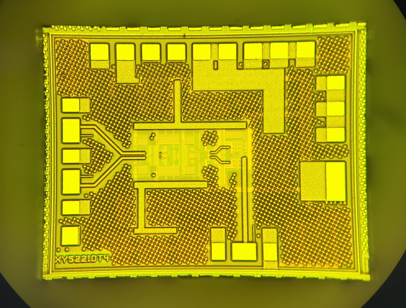
XY5221DD is One. Single Channel Laser Driver , Designed for direct modems 25Gb/s Laser Interface 。 The currents and the transients can be replaced by the currents. 2 Line Line Lines Interface Independent Programming , Meanwhile... 2 Line Interface Supports also the inclusion of programmability for balancing and cross-point adjustments , Take one. Tx Disable , It can be closed. Laser Erosion and Moderation Current , Existing IBIAS Monitor 。 This simulation output can be used to Laser Overcrowding and / or Laser Modulation Current for External Monitoring 。 There's a piece in there. ADC Functions , It can be used for foot-inducing measurements via electrical input of a special back-cover monitor TX_PWR。ADC It can also be configured for measurement. VCC( ..can measure each Power Supply ) and IBIAS( Average Laser Erosion of currents )。
-
 1CH×25G/28G EML Driver
Software and Data Services
Xy-technology
XY5221E is A high-performance piece. Single Channel 28Gbps EML Driver 。 It provides daring. 30GHz High bandwidth and greater than 2.5Vpp and the output range , The cost of the operation is about 0.17W。 It's designed for use in... Drive EML Laser , The chip is available in nudity chip form. 。
-
 4CH×25G/28G DML Driver
Software and Data Services
Xy-technology
XY5224DD is One. Four Channel Laser Driver , Designed for direct modems 25Gb/s Laser Interface 。 The currents and the transients can be replaced by the currents. 2 Line Line Lines Interface Independent Programming , Meanwhile... 2 Line Interface Supports also the inclusion of programmability for balancing and cross-point adjustments , Take one. Tx Disable , It can be closed. Laser Erosion and Moderation Current , Existing IBIAS Monitor 。 This simulation output can be used to Laser Overcrowding and / or Laser Modulation Current for External Monitoring 。 There's a piece in there. ADC Functions , It can be used for foot-inducing measurements via electrical input of a special back-cover monitor TX_PWR。ADC It can also be configured for measurement. VCC( ..can measure each Power Supply ) and IBIAS( Average Laser Erosion of currents )。
-
4CH×25G/28G EML Driver
Software and Data Services
Xy-technology
XY5224E is A high-performance piece. Four Channel 28Gbps EML Driver 。 It provides daring. 30GHz High bandwidth and greater than 2.5Vpp and the output range , The cost of the operation is about 0.45W。 It's designed for use in... Drive EML Laser , The chip is available in nudity chip form. 。
-
 25G/28G CDR+VCSEL Driver
Software and Data Services
Xy-technology
XY5921V Integration VCSEL Driver 、 Balancer and clock data recovery 。 None The reference clock will support it. 24.3Gbps Present. 28.1Gbps Rate range , It's also possible. bypass Mode supports lower rate 。 The chip is provided in nudist form. 。
Related Articles
Driven by the continuous pursuit of higher precision and efficiency in optical communication and optoelectronic device manufacturing, OLCR-1000 Low-Coherence Interferometer, independently developed by Wuhan Guanggu Interconnect Technology Co., Ltd., provides an innovative technical solution for distributed return loss testing of optical fibers and optoelectronic devices.
icrolight is a high-tech enterprise specializing in the R&D, manufacturing and sales of active and passive photonic devices for microwave photonics, LiDAR ranging, gas sensing, fiber optics and photomedicine.
BEIJING JIEPU TREND supplies YAG+Er:YAG+YAG bonded composite slab laser crystals for high‑power solid‑state laser systems. The monolithic slab consists of two undoped YAG end‑cap layers and a central Er‑doped YAG gain segment. The overall dimension is 9 mm×9 mm×9 mm.
Shanghai Connet Laser Technology Co., Ltd. focuses on technological innovation, delivering cutting-edge photonic products & solutions for industrial lasers, LiDAR, fiber optic sensing, coherent telecom, cold atom physics and precision spectroscopy research & mass manufacturing.
Loading...
Name
Phone
Organization
Use Case

Database Platform