
100G PicoMetrix CR-100D Coherent receiver
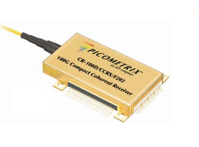
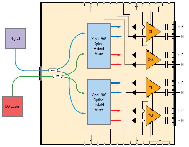
The PicoMetrix CR-100D 100Gbps DPQPSK polarization-maintaining coherent receiver integrates a demodulator, balanced detectors and bandwidth adjustment in an ultracompact package, supporting DP-QPSK in 100Gbps/200Gbps coherent systems. The PicoMetrix CR-100D 100Gbps PM-QPSK polarization-maintaining coherent receiver integrates an optical hybrid and balanced detectors in an ultracompact package, supporting DP-QPSK in 100Gbps/200Gbps coherent systems. 100Gbps Coherent DP-QPSK Receiver, PicoMetrix CR-100D, PBS and 90Deg. Hybrid Integrated The coherent receiver module CR-100D consists of an integrated polarization beam splitter and four balanced photo-receivers monolithically integrated with optical 90° hybrids. The receiver is a fully differential optical front-end suited for 100 Gbit/s DP-QPSK applications featuring high linearity and high common mode rejection ratio. The optical 90° hybrids demodulate the I/Q incident signal for each respective polarization state using external reference oscillator laser sources. The mixing products are detected by PIN-photodiodes and amplified by trans-impedance amplifiers (TIA) with linear transfer characteristics.
 Save to Favorites
Overview
Specifications
| Parameter | Value |
|---|---|
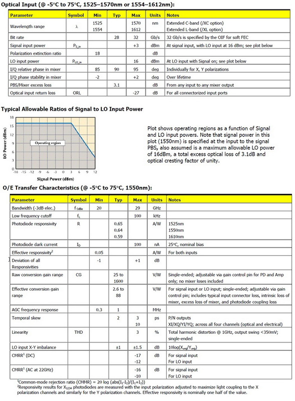
| Wavelength range λ [Optical Input /T=-5°C to75°C; wavelength interval as explicitly specified per XC/XL option / Extended C-band(XC option)] | 1525–1570 nm |
| Wavelength range λ [Optical Input /T=-5°C to75°C; wavelength interval as explicitly specified per XC/XL option / Extended L-band(XL option)] | 1554–1612 nm |
| Bit rate [Optical Input /T=-5°C to75°C; wavelength interval as explicitly specified per XC/XL option / 32Gb/s is specified by the OIF for soft FEC] | typical:28 Gb/s;max:32 Gb/s |
| Signal input power P_S_in [Optical Input /T=-5°C to75°C; wavelength interval as explicitly specified per XC/XL option / At signal input,with LO input at16dBm; plot-derived operating boundaries not extracted] | max:+3 dBm |
| Polarization extinction ratio [Optical Input /T=-5°C to75°C; wavelength interval as explicitly specified per XC/XL option] | min:18 dB |
| LO input power P_LO_in [Optical Input /T=-5°C to75°C; wavelength interval as explicitly specified per XC/XL option / At LO input with Signal on; no plot-derived bounds] | max:16 dBm |
| I/Q relative phase in mixer [Optical Input /T=-5°C to75°C; wavelength interval as explicitly specified per XC/XL option / Individually for X,Y polarizations] | min:85 deg;typical:90 deg;max:95 deg |
| I/Q phase stability in mixer [Optical Input /T=-5°C to75°C; wavelength interval as explicitly specified per XC/XL option / Over lifetime] | min:-2 deg;max:+2 deg |
| PBS/Mixer excess loss [Optical Input /T=-5°C to75°C; wavelength interval as explicitly specified per XC/XL option / From any input to any mixer output] | typical:3.1 dB |
| Optical input return loss ORL [Optical Input /T=-5°C to75°C; wavelength interval as explicitly specified per XC/XL option / For all connectorized input ports] | max:-27 dB |
| Bandwidth(-3dB elec.) f_-3dBe [O/E Transfer Characteristics /T=-5°C to75°C /λ=1550nm] | min:20 GHz;max:29 GHz |
| Low frequency cutoff f_L [O/E Transfer Characteristics /T=-5°C to75°C /λ=1550nm] | max:100 kHz |
| Photodiode responsivity | typical:0.65 A/W |
| Photodiode responsivity | typical:0.64 A/W |
| Photodiode responsivity | typical:0.59 A/W |
| Photodiode dark current I_D [25°C,nominal bias; O/E table headingλ1550nm] | max:100 nA |
| Effective responsivity | min:0.05 A/W |
| Deviation of all Responsivities [O/E Transfer Characteristics /T=-5°C to75°C /λ=1550nm] | min:-1 dB;max:+1 dB |
| Raw conversion gain range CG [O/E Transfer Characteristics /T=-5°C to75°C /λ=1550nm /Single-ended;adjustable via gain control pin for PD and Amp only;no mixer losses included] | typical:25 to1600 V/W |
| Effective conversion gain range | typical:2.6 to88 V/W |
| AGC frequency response [O/E Transfer Characteristics /T=-5°C to75°C /λ=1550nm] | min:0.3 MHz;typical:1 MHz |
| Temporal skew [O/E Transfer Characteristics /T=-5°C to75°C /λ=1550nm /P/N outputs] | typical:2 ps;max:3 ps |
| Temporal skew [O/E Transfer Characteristics /T=-5°C to75°C /λ=1550nm /XI/XQ/YI/YQ;across all four channels(optical and electrical)] | max:10 ps |
| Linearity THD [O/E Transfer Characteristics /T=-5°C to75°C /λ=1550nm /Total harmonic distortion@1GHz,output swing<350mV,single-ended] | max:3 % |
| LO input X-Y imbalance [O/E Transfer Characteristics /T=-5°C to75°C /λ=1550nm /10log(X_avg/Y_avg)] | typical:±1 dB;max:±1.5 dB |
| CMRR(DC) [O/E Transfer Characteristics /T=-5°C to75°C /λ=1550nm / For signal input / Common-mode rejection ratio(CMRR)=20log(abs(I1-I2)/(I1+I2))] | max:-17 dB |
| CMRR(DC) [O/E Transfer Characteristics /T=-5°C to75°C /λ=1550nm / For LO input / Common-mode rejection ratio(CMRR)=20log(abs(I1-I2)/(I1+I2))] | max:-12 dB |
| CMRR(AC at22GHz) [O/E Transfer Characteristics /T=-5°C to75°C /λ=1550nm / For signal input / Common-mode rejection ratio(CMRR)=20log(abs(I1-I2)/(I1+I2))] | max:-16 dB |
| CMRR(AC at22GHz) [O/E Transfer Characteristics /T=-5°C to75°C /λ=1550nm / For LO input / Common-mode rejection ratio(CMRR)=20log(abs(I1-I2)/(I1+I2))] | max:-10 dB |
Applications
Key Features
Datasheet
Please provide your email to download the datasheet.
Invalid email format. Please try again.
Supplier Information
Related Products
-
 Fiber-Optic Transceiver LF-121S-25KM
Transmitters and Receivers
Lifo-fj
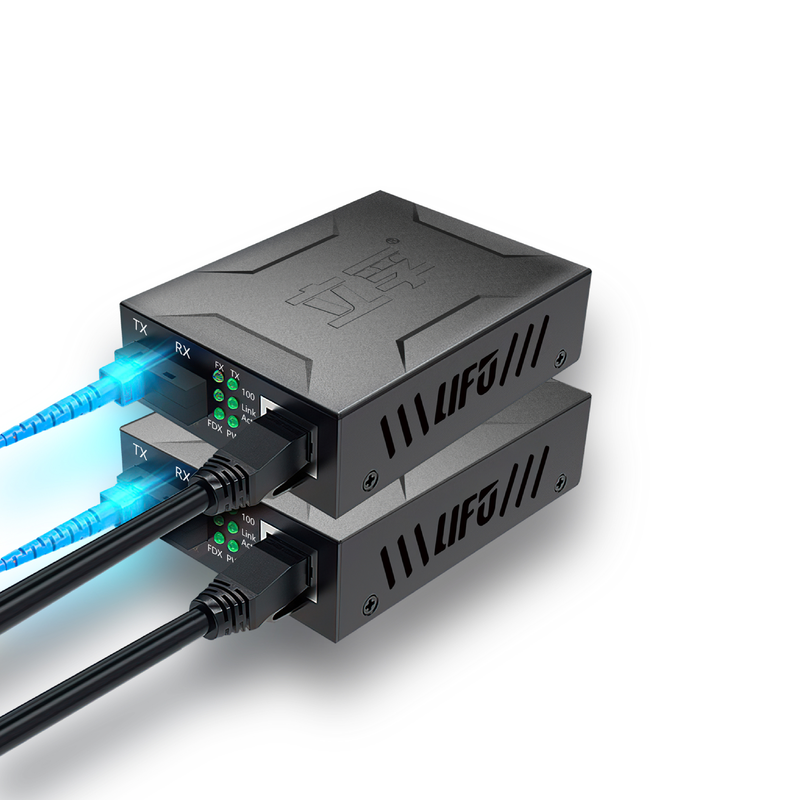
Fiber interface: SC Single-Mode Dual-Fiber Fiber wavelength: 1310nm Optical fiber Rate: 100M
-
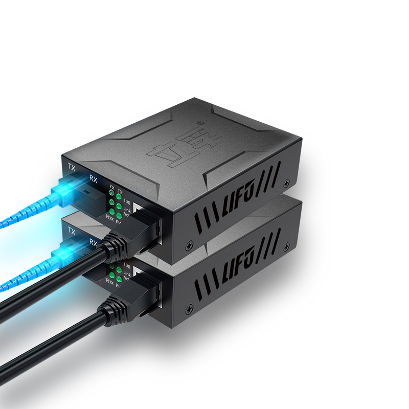 Fiber-Optic Transceiver LF-211S-20KM A
Transmitters and Receivers
Lifo-fj
Fiber interface: SC Single-Mode Single-Fiber Fiber wavelength [Transmit]: 1310nm Fiber wavelength [Reception]: 1550nm
-
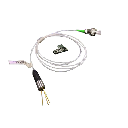 1.25G~10G 1550nm Coaxial Laser Assembly OLD-5-X-X-X-X-X-X-XX-X-X-XX
Transmitters and Receivers
O-send
Absolute Maximum Ratings - Storage Temperature: -40~+85°C Absolute Maximum Ratings - Operating temperature: -20°C~+70°C Absolute Maximum Ratings -LD Forward Current: 120mA
For test/measurement and OTDR;1550nm with built-in monitor PD.
-
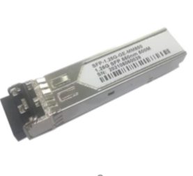 1000BASE SFP SR(850nm 550M) OSFP-108505
Transmitters and Receivers
O-send
Emission wavelength: 850nm Specification: 550m
This enhanced SFP transceiver includes DDM and meets Ethernet requirements for 1.25Gbps communications. Alarms/warnings follow SFF-8472 MSA version 10.4 through I2C. It supports 1.25G at 850nm over up to 550m of multimode fiber. Subwatt consumption and excellent EMI enable dense ports. RoHS compliance and industry safety design/testing include Class I laser conformity with US FDA/CDRH and IEC-60825. The SFP SR connects to a standard 20-contact SFP connector for hot swapping, allowing maintenance/configuration without host power removal. Transmit/receive DATA interfaces are internally AC-coupled. LV-TTL transmitter-disable input and LOS output are provided. A pull-ring latch enables easy release and meets SFP MSA. A +3.3V supply supports case temperatures 0°C to +70°C commercial or -40°C to +85°C industrial. A metal housing shields EMI.
-
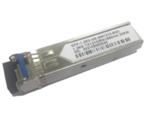 1000Base SFP BIDI Module(1310nm/1550nm 20Km) OSFP-1131520
Transmitters and Receivers
O-send
Emission wavelength: 1310nm/1550nm Specification: 20KM
This enhanced small-form-factor pluggable (SFP) fiber transceiver includes digital diagnostic monitoring (DDM). It complies with Ethernet standards and is ideal for 1.25Gbps data communications. DDM alarms and warnings are integrated through an I2C serial interface under the SFF-8472 multisource agreement (MSA), version 10.4. The transceiver supports 155Mbps to 1.25Gbps and provides a solution for 1310nm transmission over up to 20 kilometers of single-mode fiber. Subwatt consumption and excellent EMI performance support high port density. It is RoHS compliant and designed and tested to industry safety standards, and is a Class I laser product under US FDA/CDRH and international IEC-60825 standards. The SFP LR connects to a standard 20-contact SFP connector for hot swapping, allowing configuration changes or maintenance by replacing the transceiver without switching off the host. Transmitter and receiver DATA interfaces are internally AC-coupled. An LV-TTL transmitter-disable input and loss-of-signal (LOS) output are provided. A bail latch permits easy module removal and complies with the SFP MSA. A single +3.3V supply powers operation at case temperatures of 0°C to +70°C commercially or -40°C to +85°C industrially. The metal case protects against electromagnetic interference.
Related Articles
In photonics and laser technology, devices that manipulate optical signals via the electro-optic effect form the backbone of precision optical systems. Electro-optic phase modulators and electro-optic deflectors are two prominent examples of this device category. As a critical hardware solution for high-speed, high-accuracy laser beam direction control, electro-optic deflectors are widely deployed across industrial and research settings. Below is a detailed overview of their core structure, key performance drivers, and primary use cases.
As a top‑tier supplier of tunable laser chips, Shandong Zhongxin Optoelectronics Technology Company has newly launched the world’s first budget‑friendly fiber‑Bragg‑grating (FBG) demodulator and scanning module.
A laser bar is an array semiconductor laser chip integrated with dozens of emitters, which realizes hundred-watt quasi-continuous output on a single chip. With regular emitter arrangement and controllable fill factor, integrated thermal design and superior wall-plug efficiency compared to single chips, it acts as the core light source for high-power pumping, medical lasers and precision processing.
BEIJING JIEPU TREND supplies YAG+Er:YAG+YAG bonded composite slab laser crystals for high‑power solid‑state laser systems. The monolithic slab consists of two undoped YAG end‑cap layers and a central Er‑doped YAG gain segment. The overall dimension is 9 mm×9 mm×9 mm.
Loading...
Name
Phone
Organization
Use Case

Database Platform