
Three-temperature 800G BERT
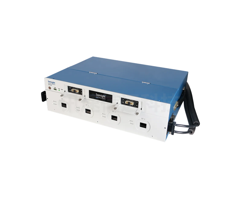
The Lianxun Instruments 800G Optical Module Tester is an integrated BER test system combining an optical port bit error analyzer (BERT) and a three-temperature control unit. It integrates multiple bit error analyzers, multiple MCBs for optical modules under test, and multiple independent temperature control units, with no need for external RF cable interconnection. Through different thermal cycling settings, high-speed optical module bit error testing under different ambient temperature conditions is achieved; through the replaceable MCB test card design, no additional high-speed RF cables are needed, enabling flexible and fast plug-in testing of the DUT; by replacing the MCB test card and matching test fixtures, testing of optical modules in different package types can be achieved, mainly including 800G QSFP-DD, OSFP and other optical modules, and also compatible with 400G optical modules; test items include optical module bit error testing, FEC testing, transmitter calibration, DMI information monitoring, voltage and current measurement, voltage modulation (bias test), etc.; the temperature cycling compression box kit specially designed for the MCB test card supports TEC temperature cycling (no load: -10~+85 ℃, loaded module DMI temperature -5~+85 ℃); high-efficiency temperature cycling testing is achieved by configuring a high-cooling-capacity water chiller; the product's excellent signal quality (fast rise/fall times, low jitter), rich functions (supporting FEC error correction analysis), flexible option configuration, and extremely high overall integration provide strong performance and flexibility guarantees for the pre-research, design, and production testing of high-speed serial circuit products.
 Save to Favorites
Overview
Specifications
| Parameter | Value |
|---|---|
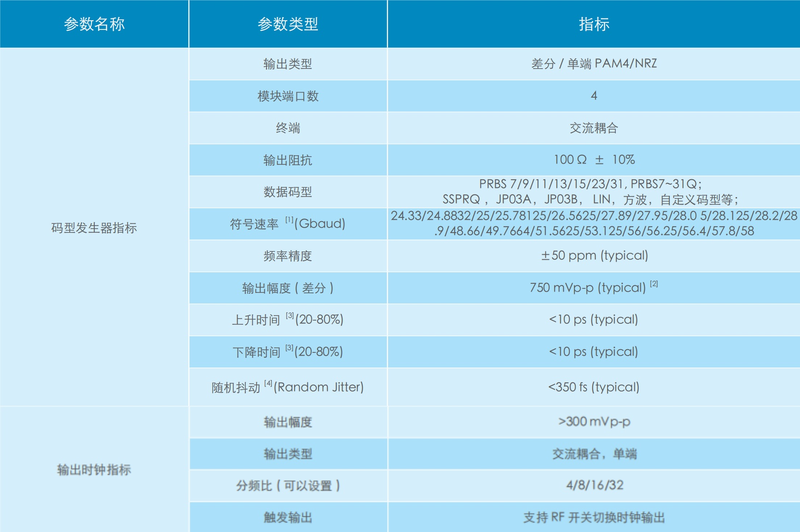
| Pattern generator - Output type | Differential/Single-ended PAM4/NRZ |
| Pattern Generator-Module Port Count | 4 |
| Pattern generator - Termination | AC coupled |
| Pattern generator - Output impedance [±10%] | 100 Ω ±10 % |
| Pattern Generator-Data Pattern | PRBS 7/9/11/13/15/23/31, PRBS7~31Q; SSPRQ, JP03A, JP03B, LIN, square wave, custom patterns, etc. |
| Pattern Generator-Symbol Rate (Gbaud) [add-on option available, supports more extended rates below 48G] | 24.33/24.8832/25/25.78125/26.5625/27.89/27.95/28.05/28.125/28.2/28.9/48.66/49.7664/51.5625/53.125/56/56.25/56.4/57.8/58 Gbaud |
| Pattern generator - Frequency accuracy [typical] | ±50 ppm (typical) |
| Pattern Generator-Output Amplitude (Differential) [differential; typical; net measured value at transmitter, default pre-emphasis/de-emphasis parameters] | 750 mVp-p (typical) |
| Pattern Generator-Rise Time (20-80%) [20-80%; typical; measured with 53.125Gbps NRZ signal] | <10 ps (typical) |
| Pattern Generator-Fall Time (20-80%) [20-80%; typical; measured with 53.125Gbps NRZ signal] | <10 ps (typical) |
| Pattern Generator-Random Jitter (Random Jitter) [typical; random jitter measured after jitter separation] | <350 fs (typical) |
| Output Clock-Output Amplitude | >300 mVp-p |
| Output Clock-Output Type | AC-coupled, single-ended |
| Output Clock-Divider Ratio (configurable) | 4/8/16/32 |
| Output Clock-Trigger Output | Supports RF switch to toggle clock output |
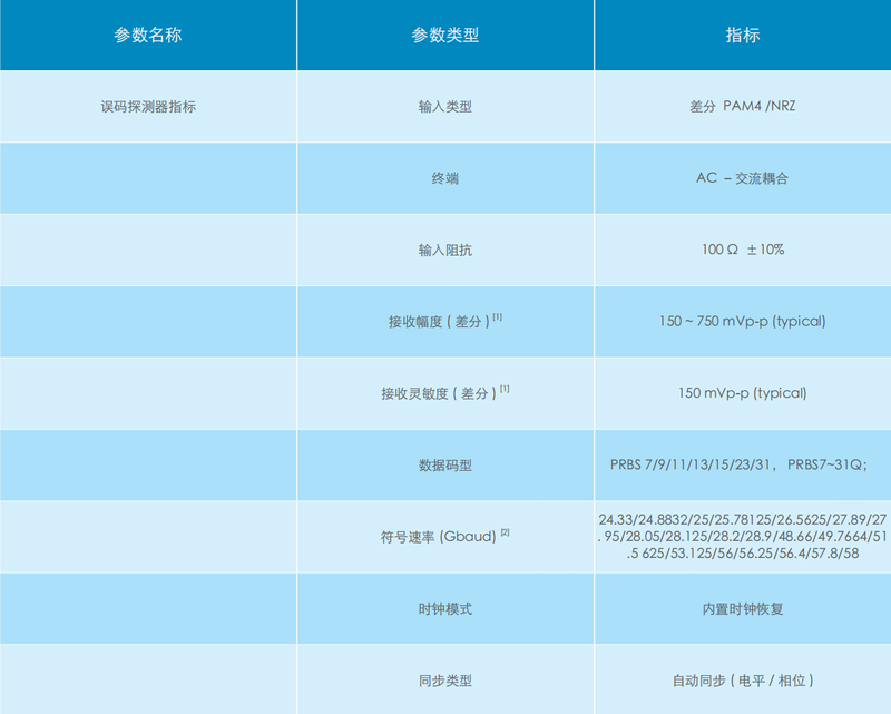
| Error detector - Input type | Differential PAM4/NRZ |
| Error detector - Termination | AC-AC-coupled |
| Error detector - Input impedance [±10%] | 100 Ω ±10 % |
| Error Detector-Receive Amplitude (Differential) [differential; typical; module measured value, excessively high voltage input may damage the receiver] | 150~750 mVp-p (typical) |
| Error Detector-Receive Sensitivity (Differential) [differential; typical; module measured value, excessively high voltage input may damage the receiver] | 150 mVp-p (typical) |
| Error detector - Data pattern | PRBS 7/9/11/13/15/23/31,PRBS7~31Q |
| Error Detector-Symbol Rate (Gbaud) [add-on option available, supports extended rates below 48G] | 24.33/24.8832/25/25.78125/26.5625/27.89/27.95/28.05/28.125/28.2/28.9/48.66/49.7664/51.5625/53.125/56/56.25/56.4/57.8/58 Gbaud |
| Error detector - Clock mode | Built-in clock recovery |
| Error Detector-Synchronization Type | Automatic synchronization (level/phase) |
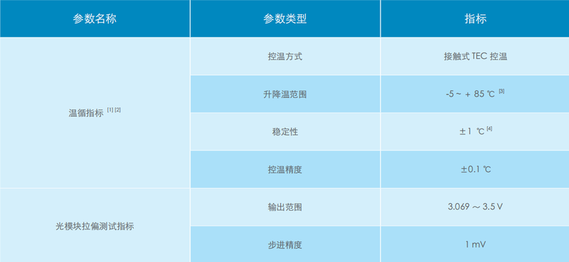
| Temperature Cycling-Temperature Control Method | Contact TEC temperature control |
| Temperature Cycling-Heating/Cooling Range | -5~+85 °C |
| Temperature Cycling-Stability | ±1 °C |
| Temperature Cycling-Temperature Control Accuracy | ±0.1 °C |
| Optical Module Bias Test-Output Range | 3.069~3.5 V |
| Optical Module Bias Test-Step Accuracy | 1 mV |
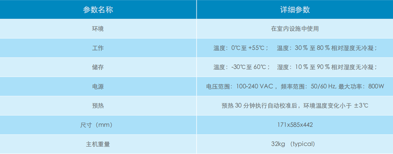
| Environment | For use in indoor facilities |
| Operating | Temperature: 0 °C to +55 °C; Humidity: 30 % to 80 % RH non-condensing |
| Storage | Temperature: -30 °C to 60 °C; Humidity: 10 % to 90 % RH non-condensing |
| Power Supply | Voltage range: 100-240VAC, Frequency range: 50/60 Hz, Maximum power: 800 W |
| Warm-up [After performing automatic calibration, ambient temperature change less than ±3°C] | After 30 minutes of warm-up and automatic calibration, ambient temperature change is less than ±3 °C |
| Dimensions | 171 mm × 585 mm × 442 mm |
| Main Unit Weight [typical] | 32 kg (typical) |
Key Features
Datasheet
Please provide your email to download the datasheet.
Invalid email format. Please try again.
Supplier Information
Related Products
-
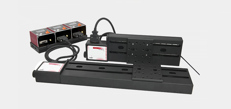 OLTS-L Series Long-Travel Linear Motion Stage OLTS-150L
Fiber Test & Measurement
Oeabt
Specifications: 352.5 mm × 100 mm × 40.5 mm Total travel: 146mm Weight: 1896.8g
This long-travel, high-precision linear stage requires an O'motion controller. (1) A high-performance two-phase stepper with microstepping gives nanometer pulse resolution. O'motion provides stepless speeds of 0.78mm/s-6.25mm/s and adjustable jog distances of 0.01-0.5mm. Jog, slow-run and Hall stepless-speed modes support precise forward/backward feed. (2) USB serial and ASCII O'motion commands support Windows, Linux, MacOS and Android. Windows host examples and complete protocol documentation facilitate secondary development. (3) Threaded and locating-pin holes allow flexible fixture installation; the USB/ASCII interface supports those operating systems. (4) Adapter plates and right-angle brackets combine stages into XY, XZ or XYZ.
-
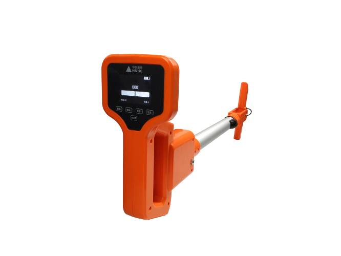 Hnhctx HY-8300 Active Optical-Cable Detector
Fiber Test & Measurement
Hnhctx
1. Detects the route and burial depth of underground optical/electrical cables. With a signal applied to cable conductors, effective detection distance is >25 kilometers at burial depths ≤1.5 meters and >10 kilometers at depths ≤2.5 meters, with horizontal position error ≤5 centimeters. 2. Detects the route and depth of underground metal pipelines, including oil, steam and water pipes. A signal applied to the pipeline or cable lead sheath gives an effective range >1000 meters. In the absence of strong magnetic interference, effective detection depth is 3 meters within a distance of 200 meters and 2.5 meters within 600 meters. 3. With a measuring probe, or grounding probe, it locates insulation faults to ground in underground plastic-jacketed optical/electrical cables. It can find leakage faults with resistance <0.5 megohms within 15 kilometers.
-
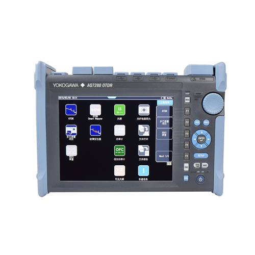 Imported Japanese Yokogawa OTDR Optical Time-Domain Reflectometer
Fiber Test & Measurement
Hnhctx
The AQ7280 series is a high-performance instrument for fiber distance/loss measurement and fault location. As field installation and maintenance demand greater reliability and ease of use, YOKOGAWA developed this new OTDR series to provide field technicians with fast, precise and convenient measurements. Safe and reliable: A rugged housing withstands harsh field conditions. A mature operating system ensures stable, responsive measurements, and protection software resists virus attacks. Easy operation: Combined multitouch and hard-key controls with new software enable automatic measurement and easy result review. Fast startup, multitasking and wireless reports improve efficiency. Multitasking: While measuring one fiber by OTDR, users can inspect another fiber's optical power and connector end face. Dual controls allow tapping, swiping, zooming and pressing on an 8.4-inch high-resolution capacitive multitouch display, or any preferred hard-key combination. Startup takes no more than 10 seconds; new high-speed hardware and efficient software ready AQ7280 within seconds. Smart Mapper: One button measures with multiple pulse widths; intelligent algorithms identify and describe line events in an icon view. User thresholds give pass/fail decisions; trace views support additional manual analysis. Available with /SMP. Multifiber measurement: A database view guides sequential tracking of multiple fibers and groups each fiber's OTDR trace, power and end-face image. Pass/fail results simplify characterization. Wireless connectivity: WindowsTM devices and wireless routers enable remote OTDR control. FlashAiTM transfers measurements to WindowsTM devices. Email/file-transfer software conveniently sends results/reports. Eagle-eye function: High sampling resolution over long distances reduces distance-offset error and precisely locates breaks, accelerating repair. Battery endurance: AQ7280 lithium batteries provide 15 hours under Telcordia conditions, or up to 10 hours with the laser continuously on. Modular design: 9 OTDR modules span single-/multimode, low to ultrahigh dynamic range, and 2 to 4 wavelengths. Users can configure power meters, light sources, visible sources and end-face probes. Connector quality: High-performance LightelTM probes visualize surfaces for scratches/contamination with magnification, inspection and comprehensive securing, reducing 90% of fiber/cable problems. PDF reports: Built-in postprocessing generates OTDR PDFs with flexible templates; wireless networking transmits them promptly. Intermittent outage monitoring: Cold-weather bending or loose connections can interrupt networks intermittently. Periodic monitoring and advanced analysis identify these events. Scheduled OTDR measurements monitor selected fibers over user-defined cycles/intervals, compare results with reference traces, analyze differences, and record the time and distance of losses exceeding user thresholds. Available with /MNT. Macrobend detection: One button acquires multiple-wavelength traces on the same fiber. Advanced analysis identifies bends when losses at the same event differ across wavelengths beyond the user threshold, immediately locating them. Fault locator: Intelligent algorithms adapt to point-to-point or PON topology to identify breaks, showing clear distance information with trace views for detail. PON optimization: Selected AQ7280 modules characterize PONs through splitters up to 1×128. PON mode helps beginners/experts configure measurements from topology information. Short event dead zones and high sampling resolution detect near-end connectors at about 0.5m, under 20 inches. The AQ7283F's built-in optical cutoff filter and dedicated port allow live PON measurement/maintenance. Multilingual display supports Chinese, Czech, Dutch, English, Finnish, French, German, Italian, Norwegian, Polish, Portuguese, Spanish, Swedish and Turkish, among others. Options: Optical and low-optical-power meters display absolute/relative source power for transmitter/network testing and save reference results. Calibration/selectable wavelengths support single-/multimode fibers and CW/modulated light. Normal and low-power options differ in specifications/functions and apply with selected OTDR units. Stable source: Selected units provide stable CW light with a power meter for precise point-to-point attenuation, plus 270Hz/1kHz/2kHz modulation for fiber identification/continuity checks. Visible source: Continuous/modulated red laser light checks patch cords, launch fibers and short links, making breaks and bends visibly identifiable.
-
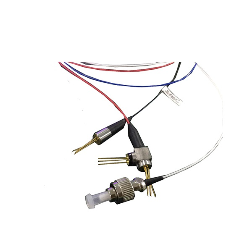 1310nm&1550nm FP and APD OTDR Module OTDR-3-5-X-X-X-XX-XX
Fiber Test & Measurement
O-send
Absolute Maximum Ratings - Storage Temperature: -40°C~+100°C Absolute Maximum Ratings - Operating temperature: -10°C~+50°C Absolute Maximum Ratings - Reverse Voltage: 2V
The 1310nm&1550nm FP and APD OTDR module is mainly used to manufacture OTDR test tools, with customization available.
-
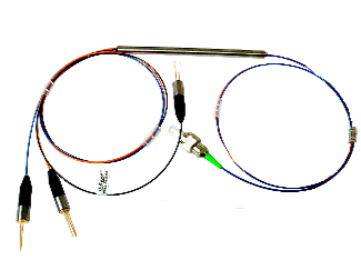 850nm&1310nm FP and APD OTDR Kit OTDR-3-8-1-X-X-XX-XXX-X
Fiber Test & Measurement
O-send
Absolute maximum ratings - Storage temperature: -40°C~+100°C Absolute maximum ratings - Operating temperature: -10°C~+50°C Absolute maximum ratings - Reverse voltage: 2V
The 850nm&1310nm FP and APD OTDR kit is mainly used in OTDR manufacturing. Customization and custom production are available.
Related Articles
As a core precision optical component for wavelength screening, frequency locking and spectral demodulation, optical etalons are widely used in high-end scientific research and precision laser equipment.
As a vital emerging sector of modern three-dimensional spatial economy, the low-altitude economy has become a new global growth driver. It covers a wide range of commercial scenarios, including UAV navigation and obstacle avoidance, precise airspace management, aerial mapping, low-altitude logistics distribution, security monitoring and emergency disaster rescue. Nevertheless, frequent extreme weather, complex terrain obstacles and increasingly dense low-altitude flight activities pose severe challenges to the safety and stability of low-altitude aircraft operations.
Laser pump sources are the core energy input component of solid-state lasers and laser amplifiers, and their performance directly determines the output power, beam quality and service life of the entire laser system. In scenarios such as industrial processing, scientific research experiments and high-end equipment, improper pump source selection will not only result in substandard system performance, but also bring a series of problems such as rapid device degradation and high operation and maintenance costs. This article sorts out the core selection logic and key pitfalls of pump source procurement, and provides selection references based on mature, mass-produced high-reliability products to help purchasers efficiently screen suitable products.
Shandong Haucore Optoelectronics Co., Ltd. introduces the HGLD‑792‑COS‑D‑10WB semiconductor laser within its COS series. Delivering an output power of 10 W at a central wavelength of 792 nm, this device adopts gold‑tin bonding COS packaging. Featuring high reliability and long service life, it serves as a preferred pump source for solid‑state lasers and is widely deployed in industrial processing, laser display, medical & aesthetic treatment, scientific research and other fields.
Loading...
Name
Phone
Organization
Use Case

Database Platform