M Series Metal Ratchet Connectors: Shock & Vibration Resistant Industrial Connection Solution
Published: 2026-08-13 15:33:41 Views: 68
Against the evolving demands for military‑grade hardware, rail transit equipment and heavy‑duty machinery that run under high‑shock vibrating conditions, anti‑loose connectors serve as indispensable hardware for stable power delivery and high‑speed signal transmission.
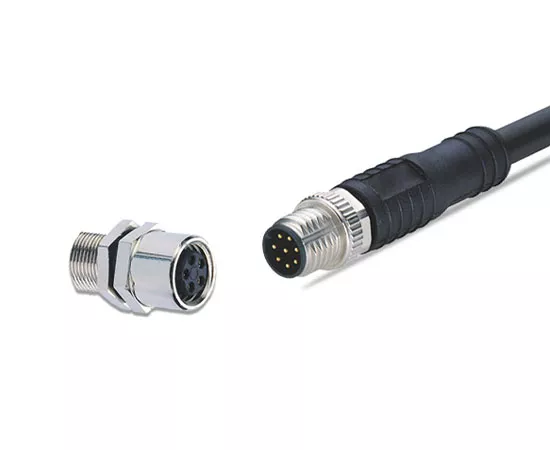
Shenzhen Tuyi Optoelectronics launches the M‑Series metal ratchet‑locking connectors fitted with proprietary triple‑start thread locking mechanics. Optimized for harsh settings featuring sustained vibration and abrupt impact loads, these connectors build dependable signal and power links for military‑defense apparatus, heavy‑duty machinery and onboard rail‑transit electronics.
This hardware balances robust locking capacity and compact lightweight housing, maximizing space‑saving benefits inside confined equipment cavities and assisting hardware engineers with internal cable layout optimization.
Core Technical Advantages
1. Anti‑Vibration Triple‑Start Thread Ratchet‑Lock Mechanism
Standard push‑pull self‑locking connectors show limited shock‑resistance performance. The standout strength of the M‑Series lies in its triple‑start thread ratchet‑lock architecture.
Multi‑start threads enable rapid hand‑tightened installation, and built‑in ratchet latches deliver rigid mechanical clamping force. The connector stays tightly mated under sudden impact loads and long‑term mechanical oscillation. It maintains continuous electrical conduction for military vehicular electronics on bumpy cross‑country travels and factory machinery exposed to persistent vibration.
2. 360‑Degree EMC‑Shielded Housing
Full‑coverage electromagnetic shielding is configured for every connector unit. Shielding effectiveness surpasses 65 dB at 100 MHz and exceeds 45 dB at 1 GHz. External radio‑frequency interference gets isolated to preserve analog control signals and high‑speed data streams from signal distortion.
3. Hermetically‑Sealed Receptacle Structure
Custom sealed receptacle assemblies suit enclosed‑structure machinery. The airtight design fends off moisture and particulate intrusion and adapts to low‑pressure or high‑pressure extreme‑atmosphere environments for specialized industrial hardware.
4. Dual Anti‑Mating Prevention: Color Coding plus Locating Pins
Two‑way mis‑insertion protection combines visual color‑mark identification and positioning latches to avoid skewed plug‑in and incorrect connection. Multiple keyway options (N, P, U, S, T) are available. When dozens of connectors are densely arranged on equipment panels, coded keyways deliver precise alignment and prevent component burnout caused by wrong insertion.
5. Multiple Terminal Assembly Options
Terminals support three assembly solutions: crimp‑on contacts, solder‑terminated wiring and PCB‑mount soldering. Hardware designers are free to select suitable terminal styles based‑on assembly workflow and internal mechanical layout.
Housing Types & Terminal Customization
Receptacle and Plug Models
Plug series: FMN, FXN, EDN, PFN, HEN, PBN
Fixed‑mount receptacles: PMN, ECN, EGN, PFN
Float‑compensated receptacles: PMN, PBN
Floating receptacles compensate for panel‑mount machining tolerances, release assembly‑induced stress and raise connector alignment fault tolerance.
Contact Terminal Configurations
Housing size codes: MM, 0M, 1M, 2M, 3M
Selectable keyways: N, P, U, S, T
Pin counts cover specifications ranging from 3 to 30 pins
Terminal installation modes: crimp‑mount, PCB soldering, wire soldering
Flexible combinations satisfy multi‑channel signal transmission and multi‑output power supply customization.
Primary Application Fields
Military & security equipment: Field communication gear, onboard electronic assemblies and portable command terminals requiring steady connections over bumpy cross‑country journeys
Heavy‑duty industrial automation: Main control modules for large‑scale machinery, industrial host controllers and signal nodes inside vibrating smart‑factory facilities
Rail transit: On‑board electronic assemblies and railway signal control systems with long‑term anti‑vibration connection requirements
Sealed special‑purpose machinery: Air‑tight receptacles for moisture‑isolated precision enclosed hardware
Material Breakdown & Electrical Specifications
Shell Raw‑Material Choices
Brass (UNS C38500): The universal substrate, finished with chrome, nickel, gold or black‑chrome anti‑corrosion plating
Stainless‑steel grades: AISI 303 general‑purpose stainless‑steel; radiation‑resistant AISI 304 for nuclear‑industry hardware; corrosion‑resistant AISI 316L for medical‑grade equipment
Light‑weight aluminium alloy (AA 6262A / AA 6023): Six optional anodized surface colours
Contact Pin Plating Standard
Male contacts adopt UNS‑C38500 brass, with a 0.5 μm copper underlayer, 3 μm nickel barrier and 1.0 μm top gold‑plated coating.
Female contacts are fabricated from beryllium copper (QQ‑C‑530) or UNS C54400 bronze. Gold‑plating thickness scales with pin diameter for optimal electrical conductivity and anti‑corrosion capability.
Insulation Substrate
High‑performance engineering plastics including PEEK, PSU, PPSU and PPS serve as insulating bases.
PEEK delivers dielectric strength of 19‑25 kV/mm, sustained operating temperature up to 250℃, V‑0 flame‑retardant rating and outstanding steam‑sterilization endurance, well‑suited for medical instruments and extreme‑temperature industrial environments。