
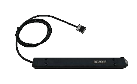
Eddy Current Displacement Sensor
The eddy-current displacement sensor is a noncontact measuring device. An excitation coil produces a high-frequency alternating magnetic field, inducing closed eddy currents in metal; detected field changes precisely measure displacement, vibration and thickness. High sensitivity, strong interference resistance, oil resistance and high-temperature tolerance support dynamic/static measurements on metal conductors of different sizes. Applications include industrial equipment monitoring, aerospace engine-blade inspection, automated dimensional control, micrometer/submicrometer positioning in semiconductor manufacturing and materials research.
 Save to Favorites
Overview
Specifications
| Parameter | Value |
|---|---|
| Resolution [General-Purpose Single-Channel Digital; One RCE211 Controller / One PS04CR(01) Probe; PDF Page 5] | ±0.05%~0.005%FSO |
| Linearity [General-Purpose Single-Channel Digital; One RCE211 Controller / One PS04CR(01) Probe; PDF Page 5] | ±0.05%~±0.2%FSO |
| Frequency Response [General-Purpose Single-Channel Digital; One RCE211 Controller / One PS04CR(01) Probe; PDF Page 5] | 22 kHz |
| System Temperature Drift [General-Purpose Single-Channel Digital; One RCE211 Controller / One PS04CR(01) Probe; PDF Page 5] | <±0.15%FSO/°C |
| Protection Rating [General-Purpose Single-Channel Digital; One RCE211 Controller / One PS04CR(01) Probe; PDF Page 5] | IP67 |
| Factory Calibration Material [General-Purpose Single-Channel Digital; One RCE211 Controller / One PS04CR(01) Probe; PDF Page 5] | 6061 Aluminum Alloy or Customer-Supplied Material |
| Number of Channels [General-Purpose Single-Channel Digital; One RCE211 Controller / One PS04CR(01) Probe; PDF Page 5] | Single Channel |
| Measurement Range [General-Purpose Single-Channel Digital; One RCE211 Controller / One PS04CR(01) Probe; PDF Page 5] | 0.28~0.46 mm |
| Signal Output [General-Purpose Single-Channel Digital; One RCE211 Controller / One PS04CR(01) Probe; PDF Page 5] | 20-Bit Digital Output (RS422) |
| Probe Operating Temperature [General-Purpose Single-Channel Digital; One RCE211 Controller / One PS04CR(01) Probe; PDF Page 5] | 0~+90 °C |
| Controller Operating Temperature [General-Purpose Single-Channel Digital; One RCE211 Controller / One PS04CR(01) Probe; PDF Page 5] | 0~+75 °C |
| Storage Temperature [General-Purpose Single-Channel Digital; One RCE211 Controller / One PS04CR(01) Probe; PDF Page 5] | -20~+90 °C |
| Dimensions [General-Purpose Single-Channel Digital; One RCE211 Controller / One PS04CR(01) Probe; PDF Page 5] | 12 cm × 10 cm × 4.5 cm |
| Cable Length [General-Purpose Single-Channel Digital; One RCE211 Controller / One PS04CR(01) Probe; PDF Page 5] | Standard 1/3/5/10 |
| Resolution [General-Purpose Dual-Channel Analog/Digital Output; One RCE223 Controller / Two PU3SA Probes; PDF Page 7] | ±0.05%~0.005%FSO |
| Linearity [General-Purpose Dual-Channel Analog/Digital Output; One RCE223 Controller / Two PU3SA Probes; PDF Page 7] | ±0.05%~±0.2%FSO |
| Frequency Response [General-Purpose Dual-Channel Analog/Digital Output; One RCE223 Controller / Two PU3SA Probes; PDF Page 7] | 22 kHz |
| System Temperature Drift [General-Purpose Dual-Channel Analog/Digital Output; One RCE223 Controller / Two PU3SA Probes; PDF Page 7] | <±0.15%FSO/°C |
| Protection Rating [General-Purpose Dual-Channel Analog/Digital Output; One RCE223 Controller / Two PU3SA Probes; PDF Page 7] | IP67 |
| Factory Calibration Material [General-Purpose Dual-Channel Analog/Digital Output; One RCE223 Controller / Two PU3SA Probes; PDF Page 7] | 6061 Aluminum Alloy or Customer-Supplied Material |
| Number of Channels [General-Purpose Dual-Channel Analog/Digital Output; One RCE223 Controller / Two PU3SA Probes; PDF Page 7] | Dual Channel (Single-Ended) |
| Measurement Range [General-Purpose Dual-Channel Analog/Digital Output; One RCE223 Controller / Two PU3SA Probes; PDF Page 7] | 0.3~3 mm |
| Signal Output [General-Purpose Dual-Channel Analog/Digital Output; One RCE223 Controller / Two PU3SA Probes; PDF Page 7] | Analog ±4.5V / 16-Bit Digital Output |
| Probe Operating Temperature [General-Purpose Dual-Channel Analog/Digital Output; One RCE223 Controller / Two PU3SA Probes; PDF Page 7] | -40~+100 °C |
| Controller Operating Temperature [General-Purpose Dual-Channel Analog/Digital Output; One RCE223 Controller / Two PU3SA Probes; PDF Page 7] | -25~+45 °C |
| Storage Temperature [General-Purpose Dual-Channel Analog/Digital Output; One RCE223 Controller / Two PU3SA Probes; PDF Page 7] | -50~+85 °C |
| Dimensions [General-Purpose Dual-Channel Analog/Digital Output; One RCE223 Controller / Two PU3SA Probes; PDF Page 7] | 76 mm × 53 mm × 35 mm |
| Cable Length [General-Purpose Dual-Channel Analog/Digital Output; One RCE223 Controller / Two PU3SA Probes; PDF Page 7] | Custom |
| Resolution [General-Purpose Dual-Channel Analog/Digital Output; One RCE223 Controller / Four PU3SA Probes; PDF Page 7] | ±0.05%~0.005%FSO |
| Linearity [General-Purpose Dual-Channel Analog/Digital Output; One RCE223 Controller / Four PU3SA Probes; PDF Page 7] | ±0.05%~±0.2%FSO |
| Frequency Response [General-Purpose Dual-Channel Analog/Digital Output; One RCE223 Controller / Four PU3SA Probes; PDF Page 7] | 22 kHz |
| System Temperature Drift [General-Purpose Dual-Channel Analog/Digital Output; One RCE223 Controller / Four PU3SA Probes; PDF Page 7] | <±0.15%FSO/°C |
| Protection Rating [General-Purpose Dual-Channel Analog/Digital Output; One RCE223 Controller / Four PU3SA Probes; PDF Page 7] | IP67 |
| Factory Calibration Material [General-Purpose Dual-Channel Analog/Digital Output; One RCE223 Controller / Four PU3SA Probes; PDF Page 7] | 6061 Aluminum Alloy or Customer-Supplied Material |
| Number of Channels [General-Purpose Dual-Channel Analog/Digital Output; One RCE223 Controller / Four PU3SA Probes; PDF Page 7] | Dual Channel (Differential) |
| Measurement Range [General-Purpose Dual-Channel Analog/Digital Output; One RCE223 Controller / Four PU3SA Probes; PDF Page 7] | 0.3~3 mm |
| Signal Output [General-Purpose Dual-Channel Analog/Digital Output; One RCE223 Controller / Four PU3SA Probes; PDF Page 7] | Analog ±4.5V / 16-Bit Digital Output |
| Probe Operating Temperature [General-Purpose Dual-Channel Analog/Digital Output; One RCE223 Controller / Four PU3SA Probes; PDF Page 7] | -40~+100 °C |
| Controller Operating Temperature [General-Purpose Dual-Channel Analog/Digital Output; One RCE223 Controller / Four PU3SA Probes; PDF Page 7] | -25~+45 °C |
| Storage Temperature [General-Purpose Dual-Channel Analog/Digital Output; One RCE223 Controller / Four PU3SA Probes; PDF Page 7] | -50~+85 °C |
| Dimensions [General-Purpose Dual-Channel Analog/Digital Output; One RCE223 Controller / Four PU3SA Probes; PDF Page 7] | 76 mm × 53 mm × 35 mm |
| Cable Length [General-Purpose Dual-Channel Analog/Digital Output; One RCE223 Controller / Four PU3SA Probes; PDF Page 7] | Custom |
| Resolution [Embedded Type; Controller RCE264 / Probe PU02SA; PDF Page 9] | ±0.05%~0.005%FSO |
| Linearity [Embedded Type; Controller RCE264 / Probe PU02SA; PDF Page 9] | ±0.05%~±0.2%FSO |
| Frequency Response [Embedded Type; Controller RCE264 / Probe PU02SA; PDF Page 9] | 22 kHz |
| System Temperature Drift [Embedded Type; Controller RCE264 / Probe PU02SA; PDF Page 9] | <±0.15%FSO/°C |
| Protection Rating [Embedded Type; Controller RCE264 / Probe PU02SA; PDF Page 9] | IP67 |
| Factory Calibration Material [Embedded Type; Controller RCE264 / Probe PU02SA; PDF Page 9] | 6061 Aluminum Alloy or Customer-Supplied Material |
| Number of Channels [Embedded Type; Controller RCE264 / Probe PU02SA; PDF Page 9] | Single Channel |
| Measurement Range [Embedded Type; Controller RCE264 / Probe PU02SA; PDF Page 9] | 0.28~0.5 mm |
| Signal Output [Embedded Type; Controller RCE264 / Probe PU02SA; PDF Page 9] | Analog 0.5~4.5V / Digital RS485 |
| Probe Operating Temperature [Embedded Type; Controller RCE264 / Probe PU02SA; PDF Page 9] | 0~+90 °C |
| Controller Operating Temperature [Embedded Type; Controller RCE264 / Probe PU02SA; PDF Page 9] | 0~+75 °C |
| Storage Temperature [Embedded Type; Controller RCE264 / Probe PU02SA; PDF Page 9] | -20~+90 °C |
| Dimensions [Embedded Type; Controller RCE264 / Probe PU02SA; PDF Page 9] | Φ12×102 |
| Cable Length [Embedded Type; Controller RCE264 / Probe PU02SA; PDF Page 9] | Optional 1/3/5m Probe, Customized Power Cable |
| Resolution [Embedded Type; Controller RCE264 / Probe PS05CR(01); PDF Page 9] | ±0.05%~0.005%FSO |
| Linearity [Embedded Type; Controller RCE264 / Probe PS05CR(01); PDF Page 9] | ±0.05%~±0.2%FSO |
| Frequency Response [Embedded Type; Controller RCE264 / Probe PS05CR(01); PDF Page 9] | 22 kHz |
| System Temperature Drift [Embedded Type; Controller RCE264 / Probe PS05CR(01); PDF Page 9] | <±0.15%FSO/°C |
| Protection Rating [Embedded Type; Controller RCE264 / Probe PS05CR(01); PDF Page 9] | IP67 |
| Factory Calibration Material [Embedded Type; Controller RCE264 / Probe PS05CR(01); PDF Page 9] | 6061 Aluminum Alloy or Customer-Supplied Material |
| Number of Channels [Embedded Type; Controller RCE264 / Probe PS05CR(01); PDF Page 9] | Single Channel |
| Measurement Range [Embedded Type; Controller RCE264 / Probe PS05CR(01); PDF Page 9] | 0.1~0.6 mm |
| Signal Output [Embedded Type; Controller RCE264 / Probe PS05CR(01); PDF Page 9] | Analog 0.5~4.5V / Digital RS485 |
| Probe Operating Temperature [Embedded Type; Controller RCE264 / Probe PS05CR(01); PDF Page 9] | 0~+90 °C |
| Controller Operating Temperature [Embedded Type; Controller RCE264 / Probe PS05CR(01); PDF Page 9] | 0~+75 °C |
| Storage Temperature [Embedded Type; Controller RCE264 / Probe PS05CR(01); PDF Page 9] | -20~+90 °C |
| Dimensions [Embedded Type; Controller RCE264 / Probe PS05CR(01); PDF Page 9] | Φ12×102 |
| Cable Length [Embedded Type; Controller RCE264 / Probe PS05CR(01); PDF Page 9] | Optional 1/3/5m Probe, Customized Power Cable |
| Resolution [Embedded Type; Controller RCE264 / Probe PS05CR(02); PDF Page 9] | ±0.05%~0.005%FSO |
| Linearity [Embedded Type; Controller RCE264 / Probe PS05CR(02); PDF Page 9] | ±0.05%~±0.2%FSO |
| Frequency Response [Embedded Type; Controller RCE264 / Probe PS05CR(02); PDF Page 9] | 22 kHz |
| System Temperature Drift [Embedded Type; Controller RCE264 / Probe PS05CR(02); PDF Page 9] | <±0.15%FSO/°C |
| Protection Rating [Embedded Type; Controller RCE264 / Probe PS05CR(02); PDF Page 9] | IP67 |
| Factory Calibration Material [Embedded Type; Controller RCE264 / Probe PS05CR(02); PDF Page 9] | 6061 Aluminum Alloy or Customer-Supplied Material |
| Number of Channels [Embedded Type; Controller RCE264 / Probe PS05CR(02); PDF Page 9] | Single Channel |
| Measurement Range [Embedded Type; Controller RCE264 / Probe PS05CR(02); PDF Page 9] | 0.1~0.6 mm |
| Signal Output [Embedded Type; Controller RCE264 / Probe PS05CR(02); PDF Page 9] | Analog 0.5~4.5V / Digital RS485 |
| Probe Operating Temperature [Embedded Type; Controller RCE264 / Probe PS05CR(02); PDF Page 9] | 0~+90 °C |
| Controller Operating Temperature [Embedded Type; Controller RCE264 / Probe PS05CR(02); PDF Page 9] | 0~+75 °C |
| Storage Temperature [Embedded Type; Controller RCE264 / Probe PS05CR(02); PDF Page 9] | -20~+90 °C |
| Dimensions [Embedded Type; Controller RCE264 / Probe PS05CR(02); PDF Page 9] | Φ12×102 |
| Cable Length [Embedded Type; Controller RCE264 / Probe PS05CR(02); PDF Page 9] | Optional 1/3/5m Probe, Customized Power Cable |
| Pin Definitions [Electrical specifications on PDF page 6; controller on the original page: RCE211; Pin 1] | +24V Supply |
| Pin Definitions [Electrical specifications on PDF page 6; controller on the original page: RCE211; Pin 2] | SWCLK |
| Pin Definitions [Electrical specifications on PDF page 6; controller on the original page: RCE211; Pin 4] | RS422_RX+ (Receive +) |
| Pin Definitions [Electrical specifications on PDF page 6; controller on the original page: RCE211; Pin 5] | RS422_RX- (Receive -) |
| Pin Definitions [Electrical specifications on PDF page 6; controller on the original page: RCE211; Pin 6] | RS422_TX- (Transmit -) |
| Pin Definitions [Electrical specifications on PDF page 6; controller on the original page: RCE211; Pin 7] | RS422_TX+ (Transmit +) |
| Pin Definitions [Electrical specifications on PDF page 6; controller on the original page: RCE211; Pin 8] | Power Ground |
| Pin Definitions [Electrical specifications on PDF page 6; controller on the original page: RCE211; Pin 9] | SWDIO |
| Pin Definitions [Electrical specifications on PDF page 8; controller on the original page: RCE224; Pin 1] | +24V Supply |
| Pin Definitions [Electrical specifications on PDF page 8; controller on the original page: RCE224; Pin 2] | GND |
| Pin Definitions [Electrical specifications on PDF page 8; controller on the original page: RCE224; Pin 3] | JTMS/SWDIO |
| Pin Definitions [Electrical specifications on PDF page 8; controller on the original page: RCE224; Pin 4] | JTCK/SWCLK |
| Pin Definitions [Electrical specifications on PDF page 8; controller on the original page: RCE224; Pin 5] | RS422_Y+ (Transmit +) |
| Pin Definitions [Electrical specifications on PDF page 8; controller on the original page: RCE224; Pin 6] | RS422_Z- (Transmit -) |
| Pin Definitions [Electrical specifications on PDF page 8; controller on the original page: RCE224; Pin 7] | RS422_B- (Receive -) |
| Pin Definitions [Electrical specifications on PDF page 8; controller on the original page: RCE224; Pin 8] | RS422_A+ (Receive +) |
| Pin Definitions [Electrical specifications on PDF page 8; controller on the original page: RCE224; Pin 11] | AGND |
| Pin Definitions [Electrical specifications on PDF page 8; controller on the original page: RCE224; Pin 12] | Analog Output (X-) |
| Pin Definitions [Electrical specifications on PDF page 8; controller on the original page: RCE224; Pin 13] | Analog Output (X+) |
| Pin Definitions [Electrical specifications on PDF page 8; controller on the original page: RCE224; Pin 14] | Analog Output (Y-) |
| Pin Definitions [Electrical specifications on PDF page 8; controller on the original page: RCE224; Pin 15] | Analog Output (Y+) |
| Pin Definitions [Embedded RCE264; PDF Page 10; Pin 1; Color: Red] | Analog Output |
| Pin Definitions [Embedded RCE264; PDF Page 10; Pin 2; Color: Gray] | RS485_B/Null |
| Pin Definitions [Embedded RCE264; PDF Page 10; Pin 3; Color: Brown] | RS485_A/Null |
| Pin Definitions [Embedded RCE264; PDF Page 10; Pin 4; Color: Blue] | +24V Supply |
| Pin Definitions [Embedded RCE264; PDF Page 10; Pin 5; Color: White] | GND |
| Pin Definitions [Embedded RCE264; PDF Page 10; Pin 6; Color: Black] | GND |
| Pin Definitions [Embedded RCE264; PDF Page 10; Pin 7; Color: Green] | JTMS/SWDIO |
| Pin Definitions [Embedded RCE264; PDF Page 10; Pin 8; Color: Yellow] | JTCK/SWCLK |
| Pin Definitions [Embedded RCE264; PDF Page 10; Pin 9; Color: Orange] | Shield / Null |
| Probe Interface [Controller RCE211; Independent Interface Labels on PDF Page 6] | IPEX Connector |
| Power Supply / Signal Output / Communication [Controller RCE211; Independent Interface Labels on PDF Page 6] | 9-Pin LEMO Connector |
| Probe Interface [Dual-Channel Section Originally Lists Controller RCE224; PDF Page 8; Not Merged with RCE223] | SMA Connector |
| Power / Signal Output / Communication Interface [Dual-Channel Section Originally Lists Controller RCE224; PDF Page 8; Not Merged with RCE223] | J30J |
| Probe Interface [Controller RCE264; Independent Interface Labels on PDF Page 10] | IPEX Connector |
| Power / Signal Output / Communication Interface [Controller RCE264; Independent Interface Labels on PDF Page 10] | 9-Pin LEMO Connector |
| Power Supply Range [Customizable Functions/Performance; Controller Structure: Single Channel - Round Tube; PDF Page 11] | 20~28 VDC |
| Target Material [Customizable Functions/Performance; Controller Structure: Single Channel - Round Tube; PDF Page 11] | Aluminum (Recommended), Steel |
| Storage Temperature [Customizable Functions/Performance; Controller Structure: Single Channel - Round Tube; PDF Page 11] | -10~+70 °C |
| Operating Temperature [Customizable Functions/Performance; Controller Structure: Single Channel - Round Tube; PDF Page 11] | 0~70 °C |
| Standard Probe and Power Cable Length [Customizable Functions/Performance; Controller Structure: Single Channel - Round Tube; PDF Page 11] | 1、3、5 |
| Special Probe and Power Cable Length [Customizable Functions/Performance; Controller Structure: Single Channel - Round Tube; PDF Page 11] | As Required |
| Interface [Customizable Functions/Performance; Controller Structure: Single Channel - Round Tube; PDF Page 11] | Lemo-9 |
| Resolution [Customizable Functions/Performance; Controller Structure: Single Channel - Round Tube; PDF Page 11] | <±0.2‰FSO |
| Linearity [Customizable Functions/Performance; Controller Structure: Single Channel - Round Tube; PDF Page 11] | <±2‰FSO |
| Normal Sampling Frequency [Customizable Functions/Performance; Controller Structure: Single Channel - Round Tube; PDF Page 11] | 20 kSa/s |
| Special Sampling Frequency [Customizable Functions/Performance; Controller Structure: Single Channel - Round Tube; PDF Page 11] | Customizable |
| Digital Interface [Customizable Functions/Performance; Controller Structure: Single Channel - Round Tube; PDF Page 11] | RS485 |
| Analog Interface [Customizable Functions/Performance; Controller Structure: Single Channel - Round Tube; PDF Page 11] | 0~10V |
| Power Supply Range [Customizable Functions/Performance; Controller Structure: Single Channel - Square; PDF Page 11] | 20~28 VDC |
| Target Material [Customizable Functions/Performance; Controller Structure: Single Channel - Square; PDF Page 11] | Aluminum (Recommended), Steel |
| Storage Temperature [Customizable Functions/Performance; Controller Structure: Single Channel - Square; PDF Page 11] | -10~+70 °C |
| Operating Temperature [Customizable Functions/Performance; Controller Structure: Single Channel - Square; PDF Page 11] | 0~70 °C |
| Standard Probe and Power Cable Length [Customizable Functions/Performance; Controller Structure: Single Channel - Square; PDF Page 11] | 1、3、5 |
| Special Probe and Power Cable Length [Customizable Functions/Performance; Controller Structure: Single Channel - Square; PDF Page 11] | As Required |
| Interface [Customizable Functions/Performance; Controller Structure: Single Channel - Square; PDF Page 11] | Lemo-9 |
| Resolution [Customizable Functions/Performance; Controller Structure: Single Channel - Square; PDF Page 11] | <±0.1‰FSO |
| Linearity [Customizable Functions/Performance; Controller Structure: Single Channel - Square; PDF Page 11] | <±1‰FSO |
| Normal Sampling Frequency [Customizable Functions/Performance; Controller Structure: Single Channel - Square; PDF Page 11] | 20 kSa/s |
| Special Sampling Frequency [Customizable Functions/Performance; Controller Structure: Single Channel - Square; PDF Page 11] | Customizable |
| Digital Interface [Customizable Functions/Performance; Controller Structure: Single Channel - Square; PDF Page 11] | RS485/422 |
| Power Supply Range [Customizable Functions/Performance; Controller Structure: Dual Channel; PDF Page 11] | 20~28 VDC |
| Target Material [Customizable Functions/Performance; Controller Structure: Dual Channel; PDF Page 11] | Aluminum (Recommended), Steel |
| Storage Temperature [Customizable Functions/Performance; Controller Structure: Dual Channel; PDF Page 11] | -10~+70 °C |
| Operating Temperature [Customizable Functions/Performance; Controller Structure: Dual Channel; PDF Page 11] | 0~70 °C |
| Standard Probe and Power Cable Length [Customizable Functions/Performance; Controller Structure: Dual Channel; PDF Page 11] | 1、3、5 |
| Special Probe and Power Cable Length [Customizable Functions/Performance; Controller Structure: Dual Channel; PDF Page 11] | As Required |
| Interface [Customizable Functions/Performance; Controller Structure: Dual Channel; PDF Page 11] | J30J-15、DB-9\DB-15 |
| Resolution [Customizable Functions/Performance; Controller Structure: Dual Channel; PDF Page 11] | <±0.025‰FSO |
| Linearity [Customizable Functions/Performance; Controller Structure: Dual Channel; PDF Page 11] | <±0.25‰FSO |
| Normal Sampling Frequency [Customizable Functions/Performance; Controller Structure: Dual Channel; PDF Page 11] | 20 kSa/s |
| Special Sampling Frequency [Customizable Functions/Performance; Controller Structure: Dual Channel; PDF Page 11] | Customizable |
| Digital Interface [Customizable Functions/Performance; Controller Structure: Dual Channel; PDF Page 11] | RS422 |
| Analog Interface [Customizable Functions/Performance; Controller Structure: Dual Channel; PDF Page 11] | ±5V |
| Dimensions [Typical Customized Solution Example; 1 Signal Conditioning Module; PDF Page 12] | Length (Interface Direction)×Width×Height <82mm×64mm×27mm |
| Input Voltage [Typical Customized Solution Example; 1 Signal Conditioning Module; PDF Page 12] | +10~+15 V |
| Output Signal Type [Typical Customized Solution Example; 1 Signal Conditioning Module; PDF Page 12] | Digital Signal |
| Data Interface Type [Typical Customized Solution Example; 1 Signal Conditioning Module; PDF Page 12] | SPI Differential Signal |
| Power Consumption [Typical Customized Solution Example; 1 Signal Conditioning Module; PDF Page 12] | <1 W |
| Weight [Typical Customized Solution Example; 1 Signal Conditioning Module; PDF Page 12] | <500 g |
| Operating Temperature [Typical Customized Solution Example; 1 Signal Conditioning Module; PDF Page 12] | -40~+60 °C |
| Storage Temperature [Typical Customized Solution Example; 1 Signal Conditioning Module; PDF Page 12] | -50~+85 °C |
| Coil Protective Housing Dimensions [Typical Customized Solution Example; 4 Sensor Probes; PDF Page 12] | Φ4.55mm*3.5mm |
| Metal Protective Housing Dimensions [Typical Customized Solution Example; 4 Sensor Probes; PDF Page 12] | Φ4.75mm*18mm |
| Measurement Range [Typical Customized Solution Example; 4 Sensor Probes; PDF Page 12] | ±0.7 mm |
| Resolution [Typical Custom Solution Example; 4 Sensor Probes; PDF Page 12; Bandwidth 1kHz] | ±0.008~±0.015 |
| Linearity [Typical Customized Solution Example; 4 Sensor Probes; PDF Page 12] | ±0.1~±0.5 |
| Frequency Response Range [Typical Customized Solution Example; 4 Sensor Probes; PDF Page 12] | 0~20 KHz |
| Connectors [Typical Customized Solution Example; 1 J30 Connector; PDF Page 12] | 9-Pin Male Connector |
| Cable Length [Typical Customized Solution Example; 1 J30 Connector; PDF Page 12] | 30 cm |
| Measurement Range [Appendix: commonly used probe configurations; component model: PU07CA; PDF pages 14–16 (not the complete sensor-system model)] | 0~0.75 mm |
| Resolution [Appendix: commonly used probe configurations; component model: PU07CA; PDF pages 14–16 (not the complete sensor-system model); at the midpoint of the measuring range] | 0.0125 μm |
| Nonlinearity [Appendix: commonly used probe configurations; component model: PU07CA; PDF pages 14–16 (not the complete sensor-system model)] | 0.75 μm |
| Measurement Range [Appendix: commonly used probe configurations; component model: PU1CA(01); PDF pages 14–16 (not the complete sensor-system model)] | 0~1 mm |
| Resolution [Appendix: commonly used probe configurations; component model: PU1CA(01); PDF pages 14–16 (not the complete sensor-system model); at the midpoint of the measuring range] | 0.0167 μm |
| Nonlinearity [Appendix: commonly used probe configurations; component model: PU1CA(01); PDF pages 14–16 (not the complete sensor-system model)] | 1 μm |
| Measurement Range [Appendix: commonly used probe configurations; component model: PS04CR(01); PDF pages 14–16 (not the complete sensor-system model)] | 0~0.4 mm |
| Resolution [Appendix: commonly used probe configurations; component model: PS04CR(01); PDF pages 14–16 (not the complete sensor-system model); at the midpoint of the measuring range] | 0.0167 μm |
| Nonlinearity [Appendix: commonly used probe configurations; component model: PS04CR(01); PDF pages 14–16 (not the complete sensor-system model)] | 1 μm |
| Measurement Range [Appendix: commonly used probe configurations; component model: PU1SA(01); PDF pages 14–16 (not the complete sensor-system model)] | 0~1 mm |
| Resolution [Appendix: commonly used probe configurations; component model: PU1SA(01); PDF pages 14–16 (not the complete sensor-system model); at the midpoint of the measuring range] | 0.0167 μm |
| Nonlinearity [Appendix: commonly used probe configurations; component model: PU1SA(01); PDF pages 14–16 (not the complete sensor-system model)] | 1 μm |
| Measurement Range [Appendix: commonly used probe configurations; component model: PU1CA(02); PDF pages 14–16 (not the complete sensor-system model)] | 0~1.425 mm |
| Resolution [Appendix: commonly used probe configurations; component model: PU1CA(02); PDF pages 14–16 (not the complete sensor-system model); at the midpoint of the measuring range] | 0.0237 μm |
| Nonlinearity [Appendix: commonly used probe configurations; component model: PU1CA(02); PDF pages 14–16 (not the complete sensor-system model)] | 1.425 μm |
| Measurement Range [Appendix: commonly used probe configurations; component model: PU1SA(02); PDF pages 14–16 (not the complete sensor-system model)] | 0~1.425 mm |
| Resolution [Appendix: commonly used probe configurations; component model: PU1SA(02); PDF pages 14–16 (not the complete sensor-system model); at the midpoint of the measuring range] | 0.0237 μm |
| Nonlinearity [Appendix: commonly used probe configurations; component model: PU1SA(02); PDF pages 14–16 (not the complete sensor-system model)] | 1.425 μm |
| Measurement Range [Appendix: commonly used probe configurations; component model: PU2SA(01); PDF pages 14–16 (not the complete sensor-system model)] | 0~2.175 mm |
| Resolution [Appendix: commonly used probe configurations; component model: PU2SA(01); PDF pages 14–16 (not the complete sensor-system model); at the midpoint of the measuring range] | 0.0363 μm |
| Nonlinearity [Appendix: commonly used probe configurations; component model: PU2SA(01); PDF pages 14–16 (not the complete sensor-system model)] | 2.175 μm |
| Measurement Range [Appendix: commonly used probe configurations; component model: PU2SA(02); PDF pages 14–16 (not the complete sensor-system model)] | 0~2.175 mm |
| Resolution [Appendix: commonly used probe configurations; component model: PU2SA(02); PDF pages 14–16 (not the complete sensor-system model); at the midpoint of the measuring range] | 0.0363 μm |
| Nonlinearity [Appendix: commonly used probe configurations; component model: PU2SA(02); PDF pages 14–16 (not the complete sensor-system model)] | 2.175 μm |
| Measurement Range [Appendix: commonly used probe configurations; component model: PU4SA; PDF pages 14–16 (not the complete sensor-system model)] | 0~4.6 mm |
| Resolution [Appendix: commonly used probe configurations; component model: PU4SA; PDF pages 14–16 (not the complete sensor-system model); at the midpoint of the measuring range] | 0.0767 μm |
| Nonlinearity [Appendix: commonly used probe configurations; component model: PU4SA; PDF pages 14–16 (not the complete sensor-system model)] | 4.6 μm |
| Measurement Range [Appendix: commonly used probe configurations; component model: PU3SA; PDF pages 14–16 (not the complete sensor-system model)] | 0~3.75 mm |
| Resolution [Appendix: commonly used probe configurations; component model: PU3SA; PDF pages 14–16 (not the complete sensor-system model); at the midpoint of the measuring range] | 0.0625 μm |
| Nonlinearity [Appendix: commonly used probe configurations; component model: PU3SA; PDF pages 14–16 (not the complete sensor-system model)] | 3.75 μm |
| Measurement Range [Appendix: commonly used probe configurations; component model: PU7SA; PDF pages 14–16 (not the complete sensor-system model)] | 0~7.5 mm |
| Resolution [Appendix: commonly used probe configurations; component model: PU7SA; PDF pages 14–16 (not the complete sensor-system model); at the midpoint of the measuring range] | 0.125 μm |
| Nonlinearity [Appendix: commonly used probe configurations; component model: PU7SA; PDF pages 14–16 (not the complete sensor-system model)] | 7.5 μm |
| Measurement Range [Appendix: commonly used probe configurations; component model: PU12SA; PDF pages 14–16 (not the complete sensor-system model)] | 0~12.2 mm |
| Resolution [Appendix: commonly used probe configurations; component model: PU12SA; PDF pages 14–16 (not the complete sensor-system model); at the midpoint of the measuring range] | 0.203 μm |
| Nonlinearity [Appendix: commonly used probe configurations; component model: PU12SA; PDF pages 14–16 (not the complete sensor-system model)] | 12.2 μm |
| Measurement Range [Appendix: commonly used probe configurations; component model: PU18SA; PDF pages 14–16 (not the complete sensor-system model)] | 0~18.5 mm |
| Resolution [Appendix: commonly used probe configurations; component model: PU18SA; PDF pages 14–16 (not the complete sensor-system model); at the midpoint of the measuring range] | 0.308 μm |
| Nonlinearity [Appendix: commonly used probe configurations; component model: PU18SA; PDF pages 14–16 (not the complete sensor-system model)] | 18.5 μm |
| Measurement Range [Appendix: commonly used probe configurations; component model: PU2CR; PDF pages 14–16 (not the complete sensor-system model)] | 0~2.175 mm |
| Resolution [Appendix: commonly used probe configurations; component model: PU2CR; PDF pages 14–16 (not the complete sensor-system model); at the midpoint of the measuring range] | 0.0362 μm |
| Nonlinearity [Appendix: commonly used probe configurations; component model: PU2CR; PDF pages 14–16 (not the complete sensor-system model)] | 2.175 μm |
| Measurement Range [Appendix: commonly used probe configurations; component model: PU07SA; PDF pages 14–16 (not the complete sensor-system model)] | 0~0.75 mm |
| Resolution [Appendix: commonly used probe configurations; component model: PU07SA; PDF pages 14–16 (not the complete sensor-system model); at the midpoint of the measuring range] | 0.0125 μm |
| Nonlinearity [Appendix: commonly used probe configurations; component model: PU07SA; PDF pages 14–16 (not the complete sensor-system model)] | 0.75 μm |
| Measurement Range [Appendix: commonly used probe configurations; component model: PU1CA; PDF pages 14–16 (not the complete sensor-system model)] | 0~1.425 mm |
| Resolution [Appendix: commonly used probe configurations; component model: PU1CA; PDF pages 14–16 (not the complete sensor-system model); at the midpoint of the measuring range] | 0.0237 μm |
| Nonlinearity [Appendix: commonly used probe configurations; component model: PU1CA; PDF pages 14–16 (not the complete sensor-system model)] | 1.425 μm |
| Measurement Range [Appendix: commonly used probe configurations; component model: PU2CA; PDF pages 14–16 (not the complete sensor-system model)] | 0~2.175 mm |
| Resolution [Appendix: commonly used probe configurations; component model: PU2CA; PDF pages 14–16 (not the complete sensor-system model); at the midpoint of the measuring range] | 0.0362 μm |
| Nonlinearity [Appendix: commonly used probe configurations; component model: PU2CA; PDF pages 14–16 (not the complete sensor-system model)] | 2.175 μm |
| Measurement Range [Appendix: commonly used probe configurations; component model: PU3CR; PDF pages 14–16 (not the complete sensor-system model)] | 0~3.75 mm |
| Resolution [Appendix: commonly used probe configurations; component model: PU3CR; PDF pages 14–16 (not the complete sensor-system model); at the midpoint of the measuring range] | 0.0625 μm |
| Nonlinearity [Appendix: commonly used probe configurations; component model: PU3CR; PDF pages 14–16 (not the complete sensor-system model)] | 3.75 μm |
| Controller Temperature Compensation Range [Selection Notes; PDF Page 13; Compensation Requires Separate Measurement Ranges] | 10~70 °C |
| Default Displacement Measurement Upload Frequency [Selection Notes; PDF Page 13; No Frequency Requirement; General Axial Detection] | 1 Hz |
| Digital Interface Frequency [Selection Precautions; PDF Page 13; Technical Confirmation Required if Exceeded] | Generally below 1KHz |
| Vibration Measurement Frequency [Selection Precautions; PDF Page 13; Technical Confirmation Required if Exceeded] | Generally below 20KHz |
| Power-Up Settling Time [Selection Notes; PDF Page 13; Depends on Test Material and Probe, Requires Specific Technical Confirmation] | As Short as 5 Minutes, as Long as 30 Minutes |
Key Features
Datasheet
Supplier Information
Related Products
-
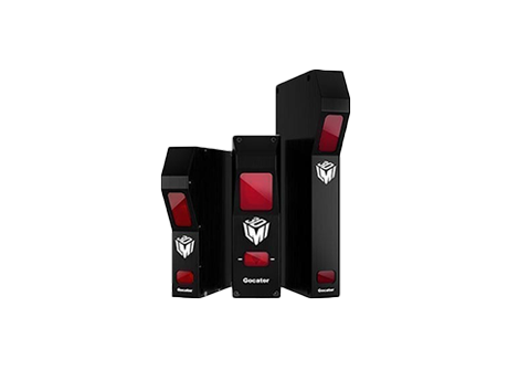 Gocator 1350 — 32kHz Laser Displacement Sensor
Displacement Gages
Daheng-imaging
Sensor Type: Point Laser Sensor Measurement Range MR: 200 mm Clear Distance: 200 mm
The Gocator 1350 smart laser Displacement Sensor is a high-speed (32kHz) laser displacement sensor from LMI. The Gocator series is designed for 3D laser ranging and is ideal for dimensional measurements, particularly height, thickness, warpage, and surface flatness. The Gocator 1350 is easy to integrate and to use in building measurement networks, making it one of the best choices for non-contact measurement applications. Designed with industrial-site conditions in mind, it is readily used in harsh industrial inline inspection and measurement environments, including industrial automation and automotive manufacturing.
-
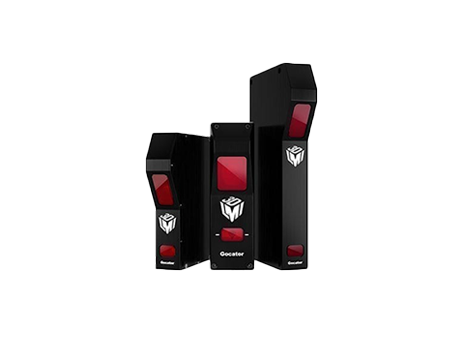 Gocator 1380 — 32kHz Laser Displacement Sensor
Displacement Gages
Daheng-imaging
Sensor Type: Point Laser Sensor Measurement Range MR: 1651 mm Clear Distance: 127 mm
The Gocator 1380 smart laser Displacement Sensor is a high-speed (32kHz) laser displacement sensor from LMI. The Gocator series is designed for 3D laser ranging and is ideal for dimensional measurements, particularly height, thickness, warpage, and surface flatness. The Gocator 1380 is easy to integrate and to use in building measurement networks, making it one of the best choices for non-contact measurement applications. Designed with industrial-site conditions in mind, it is readily used in harsh industrial inline inspection and measurement environments, including industrial automation and automotive manufacturing.
-
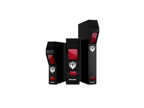 Gocator 1320 — 32kHz Laser Displacement Sensor
Displacement Gages
Daheng-imaging
Sensor Type: Point Laser Sensor Measurement Range MR: 20 mm Clear Distance: 40 mm
Gocator 1320 is LMI's high-speed 32kHz smart laser displacement sensor for 3D laser ranging and dimensional measurement, particularly height, thickness, warpage and flatness. Easy integration and measurement-network construction suit noncontact applications. Its design accommodates factory conditions and harsh inline inspection/measurement environments, including industrial automation and automotive manufacturing.
-
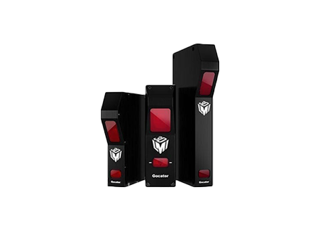 Gocator 1390 — 32kHz Laser Displacement Sensor
Displacement Gages
Daheng-imaging
Sensor Type: Point Laser Sensor Measurement Range MR: 2000 mm Clear Distance: 500 mm
The Gocator 1390 smart laser Displacement Sensor is a high-speed (32kHz) laser displacement sensor from LMI. The Gocator series is designed for 3D laser ranging and is ideal for dimensional measurements, particularly height, thickness, warpage, and surface flatness. The Gocator 1390 is easy to integrate and to use in building measurement networks, making it one of the best choices for non-contact measurement applications. Designed with industrial-site conditions in mind, it is readily used in harsh industrial inline inspection and measurement environments, including industrial automation and automotive manufacturing.
-
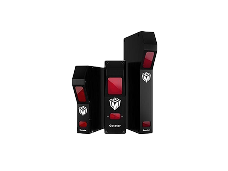 Gocator 1365 — 32kHz Laser Displacement Sensor
Displacement Gages
Daheng-imaging
Sensor Type: Point Laser Sensor Measurement Range MR: 375 mm Clear Distance: 562 mm
The Gocator 1365 smart laser Displacement Sensor is a high-speed (32kHz) laser displacement sensor from LMI. The Gocator series is designed for 3D laser ranging and is ideal for dimensional measurements, particularly height, thickness, warpage, and surface flatness. The Gocator 1365 is easy to integrate and to use in building measurement networks, making it one of the best choices for non-contact measurement applications. Designed with industrial-site conditions in mind, it is readily used in harsh industrial inline inspection and measurement environments, including industrial automation and automotive manufacturing.
Related Articles
Raybowlaser, a professional manufacturer of high-power laser chips, has officially launched its upgraded new-generation 1470nm high-performance laser chip. Achieving groundbreaking progress in rated output power and wall-plug efficiency (WPE), this innovative laser chip delivers superior and reliable core light source solutions for medical cosmetology, industrial processing, agricultural applications and scientific research equipment.
Electro-optic deflectors (EODs) are optical devices used to steer or deflect light beams by applying an electric field to a specialized optical crystal. Unlike mechanical beam steering systems that rely on moving mirrors, electro-optic deflectors enable high-speed, non-mechanical beam control with exceptional precision and responsiveness. They are widely used in laser scanning, optical communications, microscopy, laser printing, spectroscopy, and scientific research, where rapid and accurate laser beam positioning is essential.
Founded in 2004, Wuhan Union Optic Inc. is a National Specialized, Refined, Unique & Innovative "Little Giant" high-tech enterprise located in Wuhan East Lake High-Tech Development Zone.
Precise spectral screening is essential for high-precision medical detection, spectroscopic analysis and intelligent imaging systems. Tailored for visible and near-infrared spectral separation, the SP900 shortpass optical filter delivers high-efficiency light transmission and deep infrared blocking performance. It effectively eliminates stray light interference, improves signal-to-noise ratio (SNR), and serves as a core optical component for biomedical instruments, scientific analysis equipment and machine vision systems.
Loading...
Name
Phone
Organization
Use Case

Database Platform