
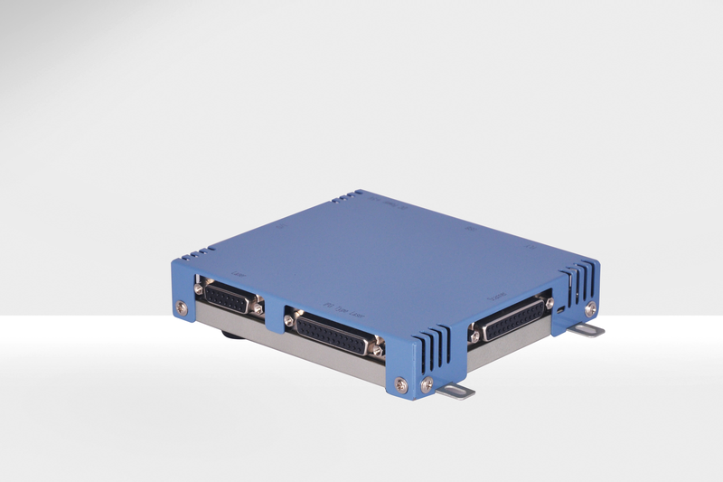
RMC2
RMC2 is a USB laser-processing control card independently developed by 鞍山精准 with fully proprietary intellectual property. A proprietary protocol communicates with scanning galvos, combining with the company's high-performance digital galvos for a solution described as 1+1>2. For difficult dynamic-focus calibration and poor corner focusing in large-area processing, preset correction files provide consistent focus across the full area without user Z-axis calibration. Applications include laser marking, welding, cladding and cleaning.
 Save to Favorites
Overview
Specifications
| Parameter | Value |
|---|---|
| Power Interface [DC Power +5V] | DC +5V 2A |
| USB | USB 2.0 Interface |
| Interface Protocol [DIP Switch to Right of Scanner Interface; RL2-100 Left, XY2-100 Right] | RL2-100/XY2-100 |
| Board Number [Customizable on Right Side of Scanner Interface] | Four-Bit Binary Number (0-15) |
| IPG Type Laser | IPG Laser Interface |
| Laser | Laser Control Interface |
| I/O | INPUT Signal Input / OUTPUT Signal Output Interface |
| FLY | On-the-Fly Marking Interface |
| Scanner | Galvanometer Control Interface |
| Interface Configuration [IPG Type Laser] | D-SUB 25 Female |
| Interface Configuration [Laser] | D-SUB 15 Female |
| Interface Configuration [INPUT/OUTPUT] | D-SUB 37 Female Connector |
| Interface Configuration [On-the-Fly Marking] | D-SUB 15 Female |
| Interface Configuration [Galvanometer Control] | D-SUB 25 Female |
| Power D0~D7 [IPG Type Laser;Pin 1-8;Output] | Power Setting:Hex0–FF or Decimal0–255;LSB(D0) Pin1,MSB(D7) Pin8;00h(0) Minimum,FFh(255) Maximum,Unconnected/Unused Equals00h;PWM Communication,Control Bus DB25.22,D1 Data,D2 Clock,Others Reserved |
| Latching [IPG Type Laser;Pin 9;Output] | Rising-Edge Active |
| Grounding [IPG Type Laser;Pin 14;/] | Grounding |
| Floating [IPG Type Laser;Pin 10、11、12、13、15、16、21、24、25;/] | Floating |
| Power Output [IPG Type Laser;Pin 17;Output] | +5V Supply Output |
| MO [IPG Type Laser;Pin 18;Output] | Master Oscillator Switch: High Level On, Low Level or Floating Off |
| Laser Modulation Input Signal [IPG Type Laser;Pin 19;Output] | Laser Modulation Input Signal |
| Pulse Repetition Frequency (Synchronization) Input Signal [IPG Type Laser;Pin 20;Output] | Pulse Repetition Frequency (Synchronization) Input Signal |
| Guidance Laser and Communication [IPG Type Laser;Pin 22;Output] | Guide Laser (Red Diode) On/Off Output; PWM Communication Control Bus, Communication Allowed Only at Low Level |
| Analogout1 [Laser;Pin 1;Output] | 0-10V Analog Output Signal for Laser Power Control |
| Analogout2 [Laser;Pin 2;Output] | 0-10V Analog Output for Laser Power Control, Independent Power Outputs for Dual-Loop Lasers |
| GND [Laser;Pin 3;/] | Reference Ground Signal |
| PWM [Laser;Pin 4;Output] | Pulse-Width Modulation Signal Sets Power by Duty Cycle; Also Usable as Pulse Repetition Frequency Signal |
| FPK [Laser;Pin 5;Output] | First-Pulse Suppression Signal, Active High |
| Laser On [Laser;Pin 6;Output] | Laser On/Off Signal, Active High |
| Leading On [Laser;Pin 7;Output] | Aiming-Light On/Off Signal, Active High |
| Lamp On [Laser;Pin 10;Output] | Master Oscillator Switch for MO Control of Certain Fiber Lasers, Active High |
| Finish [Laser;Pin 11;Output] | Marking-Complete Signal: Low during Marking, High at Other Times |
| Start [Laser;Pin 12;Input] | External Trigger Marking Start Signal; Short to pin15 to Trigger Start Command |
| Stop [Laser;Pin 13;Input] | External Trigger Marking Stop Signal; Short to pin15 to Trigger Stop Command |
| VCC [Laser;Pin 14;Output] | +5V Supply Output |
| GND [Laser;Pin 15;/] | Reference Ground Signal |
| Digital IN0 [INPUT/OUTPUT;Pin 1] | Input |
| Digital IN1 [INPUT/OUTPUT;Pin 20] | Input |
| Digital IN2 [INPUT/OUTPUT;Pin 2] | Input |
| Digital IN3 [INPUT/OUTPUT;Pin 21] | Input |
| Digital IN4 [INPUT/OUTPUT;Pin 3] | Input |
| Digital IN5 [INPUT/OUTPUT;Pin 22] | Input |
| Digital IN6 [INPUT/OUTPUT;Pin 4] | Input |
| Digital IN7 [INPUT/OUTPUT;Pin 23] | Input |
| Digital IN8 [INPUT/OUTPUT;Pin 5] | Input |
| Digital IN9 [INPUT/OUTPUT;Pin 24] | Input |
| Digital IN10 [INPUT/OUTPUT;Pin 6] | Input |
| Digital IN11 [INPUT/OUTPUT;Pin 25] | Input |
| Digital IN12 [INPUT/OUTPUT;Pin 7] | Input |
| Digital IN13 [INPUT/OUTPUT;Pin 26] | Input |
| Digital IN14 [INPUT/OUTPUT;Pin 8] | Input |
| Digital IN15 [INPUT/OUTPUT;Pin 27] | Input |
| Digital OUT0 [INPUT/OUTPUT;Pin 30] | Output |
| Digital OUT1 [INPUT/OUTPUT;Pin 12] | Output |
| Digital OUT2 [INPUT/OUTPUT;Pin 31] | Output |
| Digital OUT3 [INPUT/OUTPUT;Pin 13] | Output |
| Digital OUT4 [INPUT/OUTPUT;Pin 32] | Output |
| Digital OUT5 [INPUT/OUTPUT;Pin 14] | Output |
| Digital OUT6 [INPUT/OUTPUT;Pin 33] | Output |
| Digital OUT7 [INPUT/OUTPUT;Pin 15] | Output |
| Digital OUT8 [INPUT/OUTPUT;Pin 34] | Output |
| Digital OUT9 [INPUT/OUTPUT;Pin 16] | Output |
| Digital OUT10 [INPUT/OUTPUT;Pin 35] | Output |
| Digital OUT11 [INPUT/OUTPUT;Pin 17] | Output |
| Digital OUT12 [INPUT/OUTPUT;Pin 36] | Output |
| Digital OUT13 [INPUT/OUTPUT;Pin 18] | Output |
| Digital OUT14 [INPUT/OUTPUT;Pin 37] | Output |
| Digital OUT15 [INPUT/OUTPUT;Pin 19] | Output |
| GND [INPUT/OUTPUT;Pin 9、10、28] | Grounding |
| VCC [INPUT/OUTPUT;Pin11、29;Output] | +5V |
| Encoder A+ [On-the-fly marking; Pin 1; Input] | Encoder A+ |
| Encoder A- [On-the-fly marking; Pin 9; Input] | Encoder A- |
| Encoder B+ [On-the-fly marking; Pin 2; Input] | Encoder B+ |
| Encoder B- [On-the-fly marking; Pin 10; Input] | Encoder B- |
| GND [On-the-Fly Marking; Pin 6, 14; /] | GND |
| +5V Output [On-the-Fly Marking; Pin 7, 15, 8; Output] | +5V Output |
| CLOCK-/CLOCK+ [Galvanometer control; Pin 1/14; Output] | Differential Output, Continuous Clock |
| SYNC-/SYNC+ [Galvanometer control; Pin 2/15; Output] | Differential Output, Synchronous Data |
| CHAN1-/CHAN1+ [Galvanometer control; Pin 3/16; Output] | Differential Output, X-Axis Signal |
| CHAN2-/CHAN2+ [Galvanometer control; Pin 4/17; Output] | Differential Output, Y-Axis Signal |
| CHAN3-/CHAN3+ [Galvanometer control; Pin 5/18; Output] | Differential Output, Z-Axis Signal |
| NC [Galvanometer Control; Pin6/19, 7/20, 8/21] | NC |
| GND [Galvanometer Control; Pin11/23/24] | GND |
Applications
Key Features
Datasheet
Supplier Information
Related Products
-
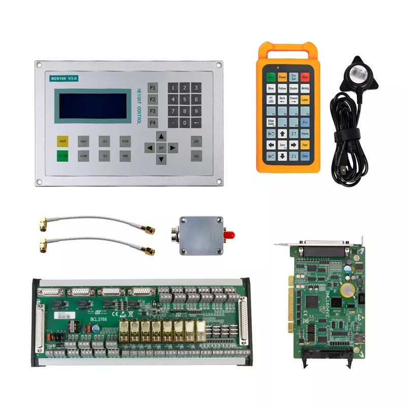 Bochu Control System
Automation and Control
Auroralaser
FSCUT2000 is a High-performance Open loop laser control system. Widely used in the field of metal and Non-metal laser cutting. Easy to install,Easy to Debug.
-
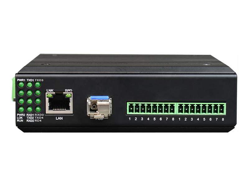 Industrial Rail-Mount 1-4-Channel RS-232/RS-422/RS-485 Serial Server
Automation and Control
Fiberwdm
Product Function Description: Transmits 1-4 RS232/422/485 serial channel(s) over Ethernet; industrial rail-mounted design Service Port Description: 1-4 RS232/422/485 Interfaces; 1 100-Megabit Ethernet Electrical Port / 1 Optical Port Power Supply: Redundant Dual Power Inputs DC9-55V or AC7-43V, Power Consumption <5W; Overload, Reverse-Polarity and Redundancy Protection Supported; 4-Pin Pluggable Terminal with 5.08mm Pitch
This IP40 industrial rail-mount serial server immediately networks serial equipment and centrally manages distributed serial devices/hosts. One to four RS-232/RS-422/RS-485 channels connect to one 100M Ethernet Comb port, offering either a 100M electrical or optical interface. 35mm rail or wall mounting suits varied sites. Protocols include TCP, UDP, ARP, ICMP, HTTP, DNS, DHCP and SNMP. Access control, quick configuration, online upgrades and web access are supported; each serial port offers four TCP connections and other modes. A Windows configuration tool guides setup step by step for easy networking. A friendly interface simplifies operation. Fanless, low-power, wide-temperature/voltage hardware passes rigorous industry-standard tests for demanding EMC environments. Uses include PLC control, building automation, healthcare automation, instruments and environmental/power monitoring.
-
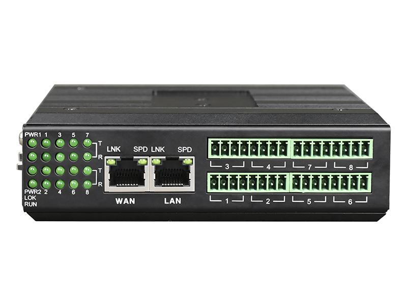 Industrial Rail-Mount 8-Channel RS-232/RS-422/RS-485 Serial Server
Automation and Control
Fiberwdm
Product Function Description: Transmits 8 RS232/422/485 serial channel(s) over Ethernet; industrial rail-mounted design Service Port Description: 8 RS232/422/485 Serial Interfaces; 2 100-Megabit Ethernet Electrical Ports Power Supply: Redundant Dual Power Inputs DC9-55V or AC7-43V, Power Consumption <5W; Overload, Reverse-Polarity and Redundancy Protection Supported; 4-Pin Pluggable Terminal with 5.08mm Pitch
This IP40 industrial rail-mount serial server immediately networks serial devices and centrally manages distributed equipment/hosts. One to eight RS-232/RS-422/RS-485 channels connect to two100M Ethernet ports for dual IP/MAC addresses, multiple-network management or backup. 35mm rail/wall mounting is supported. Protocols include TCP, UDP, ARP, ICMP, HTTP, DNS, DHCP, SNMP, Telnet, SSH and MQTT. Management offers access control, quick configuration, online upgrades and web access. Each serial port supports four TCP/UDP sessions, Modbus TCP, TCP Server/Client, UDP Server/Client and Modbus-to-MQTT. A Windows tool enables networking through simple settings, with a friendly interface. Fanless, low-power, wide-temperature/voltage hardware passes industry-standard tests for demanding EMC sites. Uses include PLC control, building/healthcare automation, instruments and environmental/power monitoring.
-
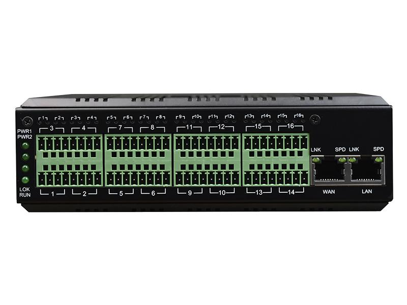 Industrial Rail-Mount 16-Channel RS-232/RS-422/RS-485 Serial Server
Automation and Control
Fiberwdm
Product Function Description: Transmits 16 RS232/422/485 serial channel(s) over Ethernet; industrial rail-mounted design Service Port Description: 16 RS232/422/485 Serial Interfaces; 2 100-Megabit Ethernet Electrical Ports Power Supply: Redundant Dual Power Inputs DC9-55V or AC7-43V, Power Consumption <5W; Overload, Reverse-Polarity and Redundancy Protection Supported; 4-Pin Pluggable Terminal with 5.08mm Pitch
This IP40 industrial rail-mount serial server immediately networks serial equipment and centrally manages distributed serial devices/hosts. It connects sixteen RS-232/RS-422/RS-485 channels to two100M Ethernet ports, supporting dual IP/MAC addresses, multiple-network management or network backup. 35mm rail or wall mounting suits varied sites. Protocols include TCP, UDP, ARP, ICMP, HTTP, DNS, DHCP, SNMP, Telnet and SSH. Access control, quick configuration, online upgrades and web access are supported. Each serial port allows four TCP/UDP sessions, with Modbus TCP, TCP Server/Client and UDP Server/Client modes. A Windows management tool simplifies configuration for easy networking through simple settings. A friendly interface is easy to operate. Fanless, low-power, wide-temperature/voltage hardware passes rigorous industry-standard tests for demanding EMC environments. Uses include PLC control/management, building automation, healthcare automation, instruments and environmental/power monitoring.
-
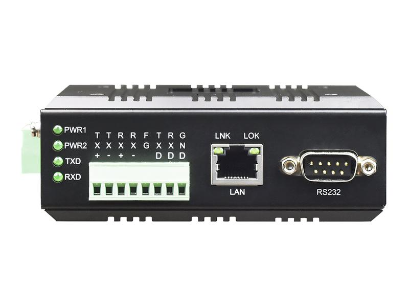 Industrial Rail-Mount 1-Channel Mini RS-232/RS-422/RS-485 Serial Server
Automation and Control
Fiberwdm
Product Function Description: Transmits 1 RS232/422/485 serial channel(s) over Ethernet; industrial rail-mounted design Service Port Description: 1 RS232/422/485 Serial Terminal Interface, 1 DB9 Male, 1 100-Megabit Ethernet Electrical Port Power Supply: DC Supply:Dual Redundant DC9–70V or AC7–50V,<5W;Overload,Reverse-Polarity and Redundancy Protection;4-Pin5.08mm Plug-In Terminal;Internal AC Supply:AC85–265V or DC110–300V,<5W;Overload Protection;Three-Position Cloverleaf AC Socket
This IP40 industrial rail-mount serial server immediately networks serial equipment and centrally manages distributed serial devices/hosts. It connects one RS-232/RS-422/RS-485 channel to one100M Ethernet port. 35mm rail or wall mounting suits varied sites. Protocols include TCP, UDP, ARP, ICMP, HTTP, DNS, DHCP and SNMP. Access control, quick configuration, online upgrades and web access are supported. Each serial port allows four TCP/UDP sessions, with Modbus TCP, TCP Server/Client and UDP Server/Client modes. A Windows management tool guides setup step by step for easy networking through simple settings. A friendly interface is easy to operate. Fanless, low-power, wide-temperature/voltage hardware passes rigorous industry-standard tests for demanding EMC environments. Uses include PLC control/management, building automation, healthcare automation, instruments and environmental/power monitoring.
Related Articles
As a core precision optical component for wavelength screening, frequency locking and spectral demodulation, optical etalons are widely used in high-end scientific research and precision laser equipment.
Shanghai Connet Laser Technology Co., Ltd. focuses on technological innovation, delivering cutting-edge photonic products & solutions for industrial lasers, LiDAR, fiber optic sensing, coherent telecom, cold atom physics and precision spectroscopy research & mass manufacturing.
A solid-state laser is one of the most common and reliable laser types used in modern industry, medical equipment, and scientific research. Unlike gas or fiber lasers, it uses solid materials as its gain medium to generate stable, high-brightness laser beams. Thanks to its high precision, long lifespan, and compact structure, solid-state lasers have become a mainstream solution for high-precision laser processing and optical systems.
Driven by worldwide energy‑structure transformation, the lithium‑ion battery industry is expanding rapidly as green, high‑efficiency energy‑storage devices gain surging global market demand. With years‑long dedication to intelligent manufacturing, Han’s Laser Lithium‑battery Intelligent Equipment has accumulated solid R&D strength and rich practical experience. By integrating multiple cutting‑edge technologies, the company delivers high‑efficiency, eco‑friendly and sustainable lithium‑ion battery production lines, bringing revolutionary upgrades to the new‑energy battery sector.
Loading...
Name
Phone
Organization
Use Case

Database Platform