

Imaging AO System
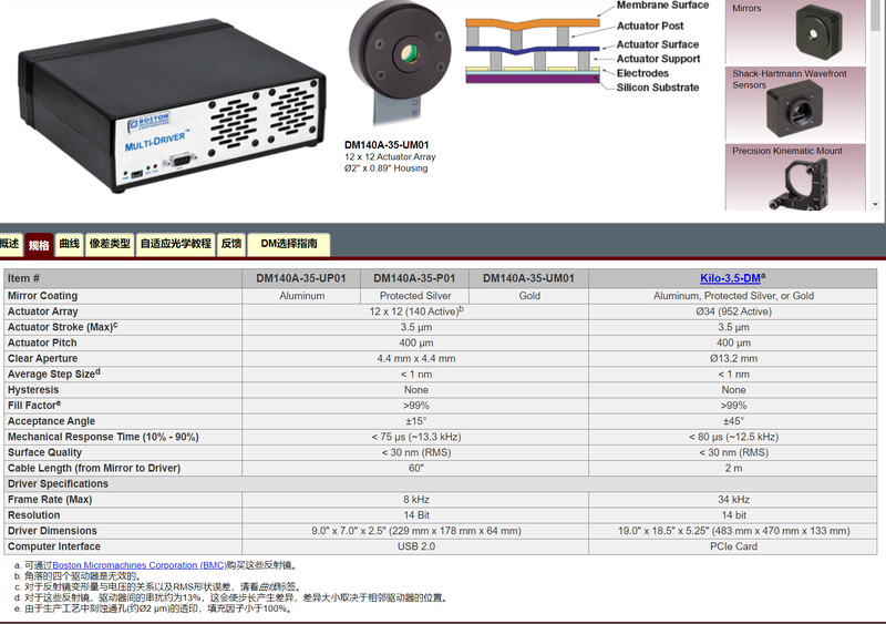
An imaging AO system mainly consists of three major parts: a deformable mirror, a composite wavefront sensor, and a wavefront processor. We offer three solutions. AO System Solution One The composite wavefront sensor is independently developed by the company, with a development cycle of approximately 8 weeks. (1) IOE-developed deformable mirror configuration parameters (2) Composite wavefront sensor The sensor includes Hartmann wavefront detection, near-field detection, and far-field detection modules. The near-field module is an auxiliary optical-path adjustment option. (3) AO real-time correction processor Two types of adaptive-optics real-time closed-loop correction processor are available: 1) X86+Linux architecture An industrial computer and image-acquisition card are used. A real-time processing patch is added to the Linux kernel, with real-time computation in the driver layer. Qt-based upper-level control algorithms provide interaction. AO system configuration and algorithm changes are relatively easy, making it suitable for experiments investigating AO closed-loop correction algorithms. 2) DSP+FPGA architecture Real-time signal-processing boards run flashed AO closed-loop firmware. External TCP/UDP protocols load common parameters and configuration files. The system is compact and convenient, but algorithm modifications are more difficult, making it suitable for mature, stable product projects. II. AO System Solution Two Deformable mirror parameters The independently developed composite wavefront sensor takes approximately 6 weeks. Parameters are consistent with configuration 1, with some differences depending on detection type; parameters are consistent with configuration 1, approximately 6 weeks. III. AO System Solution Three The independently developed composite wavefront sensor takes approximately 6 weeks. Parameters are consistent with configuration 1, with some differences depending on detection type; parameters are consistent with solution one, approximately 6 weeks.
 Save to Favorites
Overview
Specifications
| Parameter | Value |
|---|---|
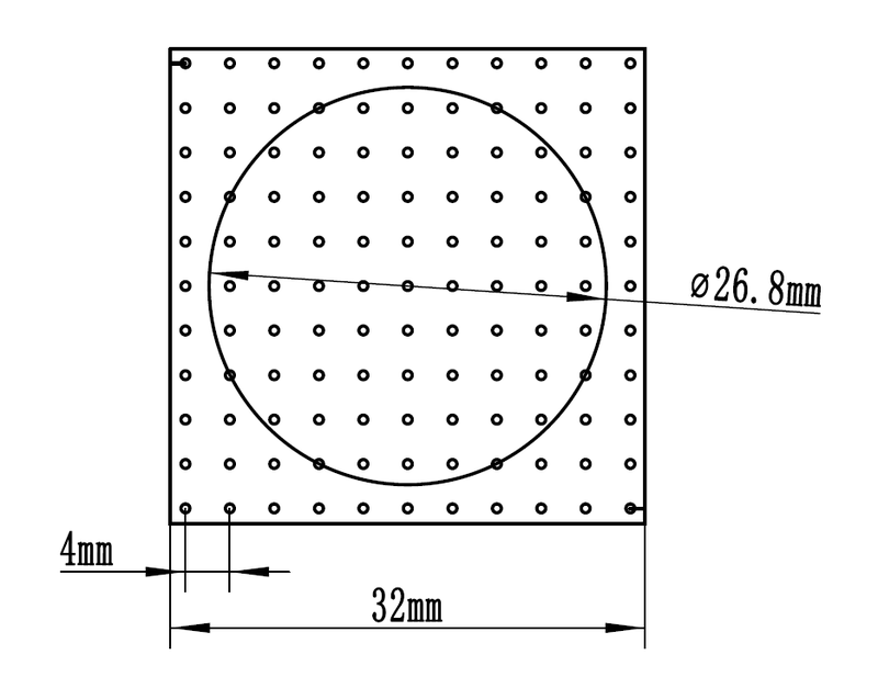
| IOE-Developed Deformable Mirror - Mirror Size [AO system solution one] | 32mm×32mm |
| IOE-Developed Deformable Mirror - Effective Beam Aperture [AO system solution one] | Square :28mm×28mm, Circular :φ26.8mm |
| IOE-Developed Deformable Mirror - Operating Incidence Angle [AO system solution one] | ±22.5° |
| IOE-Developed Deformable Mirror - Actuator Arrangement [AO system solution one] | Square 11×11 |
| IOE-Developed Deformable Mirror - Actuator Type [AO system solution one] | Piezoelectric ceramic |
| IOE-Developed Deformable Mirror - Actuator Stroke [AO system solution one; 22.5° incidence can produce approximately 9μm optical path difference modulation] | ±2.5μm (22.5° incidence can produce approximately 9μm optical path difference modulation) |
| IOE-Developed Deformable Mirror - Actuator Stroke Resolution [AO system solution one] | <0.5nm |
| IOE-Developed Deformable Mirror - Operating Frequency [AO system solution one] | >5kHz |
| IOE Independently Developed Deformable Mirror - Surface Figure RMS [AO system solution one; self-leveling flat type] | Self-leveling flat type, RMS<20nm |
| IOE Independently Developed Deformable Mirror - Coating Stack [AO system solution one; @500~1500nm; customizable] | Enhanced aluminum coating, broadband reflectance R>90%@500~1500nm (customizable) |
| IOE-Developed Deformable Mirror - Drive Power Supply Data Interface [AO system solution one] | Ethernet port, optical fiber |
| IOE-Developed Deformable Mirror - Drive Power Supply Dimensions [AO system solution one; smaller enclosure customizable] | Standard 4U enclosure (smaller enclosure customizable) |
| Composite Wavefront Sensor - Clear Aperture [AO system solution one] | Square :28mm×28mm, Circular :φ26.8mm |
| Composite Wavefront Sensor - Wavefront Detection Range PV [AO system solution one] | PV>30μm |
| Composite Wavefront Sensor - Wavefront Detection Accuracy [AO system solution one; @full aperture] | ~0.05λ @ full aperture |
| Composite Wavefront Sensor - Operating Wavelength [AO system solution one] | (Coating system selected according to the operating wavelength) |
| Composite Wavefront Sensor - Working Field of View [AO system solution one] | ±3′ |
| Composite Wavefront Sensor - Internal Modules [AO system solution one] | 1. Wavefront detection module; 2. Far-field optical-axis detection module; 3. Near-field detection module |
| Composite Wavefront Sensor - Wavefront Detection Module - Subaperture Size (Object Plane) [AO system solution one] | 2mm×2mm |
| Composite Wavefront Sensor - Wavefront Detection Module - Microlens/Subaperture Array Size [AO system solution one] | ≥15×15, Square |
| Composite Wavefront Sensor - Wavefront Detection Module - Individual Microlens Size [AO system solution one] | 2mm×2mm |
| Composite Wavefront Sensor - Wavefront Detection Module - Individual Microlens Focal Length [AO system solution one; designed according to the operating wavelength] | f=~15mm (designed according to the operating wavelength) |
| Composite Wavefront Sensor - Wavefront Detection Module - Pixel Count per Subaperture [AO system solution one] | >50×50 |
| Composite Wavefront Sensor - Wavefront Detection Module - Photodetector [AO system solution one] | Selected according to the operating wavelength and detection-frequency requirements |
| Composite Wavefront Sensor - Far-Field Module - Focal Length [AO system solution one; selected according to the operating wavelength] | 568mm (selected according to the operating wavelength) |
| Composite Wavefront Sensor - Far-Field Module - Photodetector [AO system solution one] | Selected according to the operating wavelength |
| Composite Wavefront Sensor - Far-Field Module - Field of View [AO system solution one] | ±1.5′ |
| Composite Wavefront Sensor - Additional Components [AO system solution one] | Allow for attenuator space and position |
| Composite Wavefront Sensor - Additional Components [AO system solution one] | The wavefront detector module considers adding a narrowband filter before the microlens |
| Composite Wavefront Sensor - Center Height [AO system solution one] | Determined according to sensor size |
| AO Real-Time Correction Processor - X86+Linux Architecture - Real-Time Processing Capacity [AO system solution one] | Subaperture count ~1000; 300-unit actuator class; processing frame rate >300Hz |
| AO Real-Time Correction Processor - X86+Linux Architecture - Correction Residual [AO system solution one] | RMS<0.05λ |
| AO Real-Time Correction Processor - DSP+FPGA Architecture - Correction Residual [AO system solution one] | RMS<0.05λ |
Datasheet
Please provide your email to download the datasheet.
Invalid email format. Please try again.
Supplier Information
Related Products
-
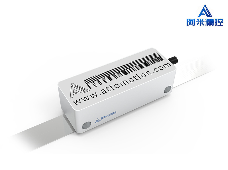 ALR Series Optical Linear Encoder Sensor
Sensors
Attomotion
Resolution [Lined system]: 12.5nm( Lined system ) Resolution [Rotate System]: 0.08arcsec( Rotate System ) Electronic analysis error: <25
Absolute nanometers Optical Linear Encoder Sensor Design based on Ami's API measurement system , Non-contact measurement achieved , It's got a very high resolution. , Meeting the measurement needs of nanoscales in various applications 。
-
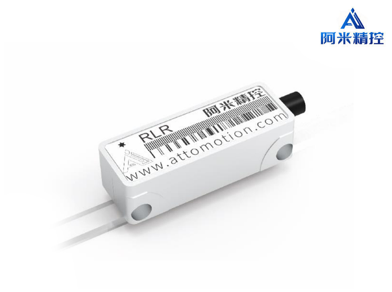 RLR Series Optical Linear Encoder Sensor
Sensors
Attomotion
Resolution [Lined system]: 12.5nm( Lined system ) Resolution [Rotate System]: 0.08arcsec( Rotate System ) Electronic analysis error: <25
Relative nanometers Optical Linear Encoder Sensor Design based on Ami's API measurement system , Non-contact measurement achieved , It's got a very high resolution. , Meeting the measurement needs of nanoscales in various applications 。
-
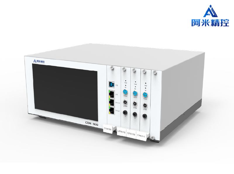 Three Channel Sensor Main Unit CDM-300 CDM300
Sensors
Attomotion
Fits the detectives.: PC06-100/ PC10-200/ PC20-2000 Channels: 3 Output: Communications : USB, Ethernet, EtherCAT, CAN, RS232 Real time : SPI
•CDM-300 Controller CDM-300 Microshift Sensor Main Unit Special Compact Application Design , Internal Preamplifier 、 Filters and signal adjust circuits , And for the right spot. Drive Optimization , Fit for integrated application 。 Here. Multichannel Controller It's the core. Capacitive Microdisplacement Sensor Super-precision measurement applications for high-requirement indicators 。 Embedding different working patterns to adapt to measurements based on static indicators and to the measurement of the measurement of the measurement of the measurement of the measurement of the measurement of the measurement of the measurement of the measurement of the measurement of the measurement of the measurement of the measurement of the measurement of the measurement of the measurement of the measurement of the measurement of the measurement of the measurement of the measurement of the measurement of the measurement of the measurement of the measurement of the measurement of the measurement of the measurement of the measurement of the measurement of the use of the measurement of the measurement of the use of the measurement of the measurement of the measurement of the measurement of the measurement of the measurement of the measurement of the use of the measurement of the measurement of the use of the use of the measurement of the measurement of the measurement of the measurement of the use of the measurement of the measurement of the measurement of the measurement of the use of the use of the use of the use of the use of the use of the measurement of the measurement of the measurement of the measurement of the measurement of the measurement of the measurement of the measurement of the use of the measurement of the static indicators of the measurement of the use of the use of the use of the use of the use of the use of the use of the use of the use of the use of the use of the use of the use of the use of the use of the use of the use of the measurement of the Dynamic Indicator-based real-time applications , And balance. Dynamic and static indicators for high bandwidth super-precision feedback control systems 。 Multichannel Controller Inline Channel Synchronization , Support 3 Synchronization of the channel , For thickness detection 、 Rotation bias correction etc. 。
-
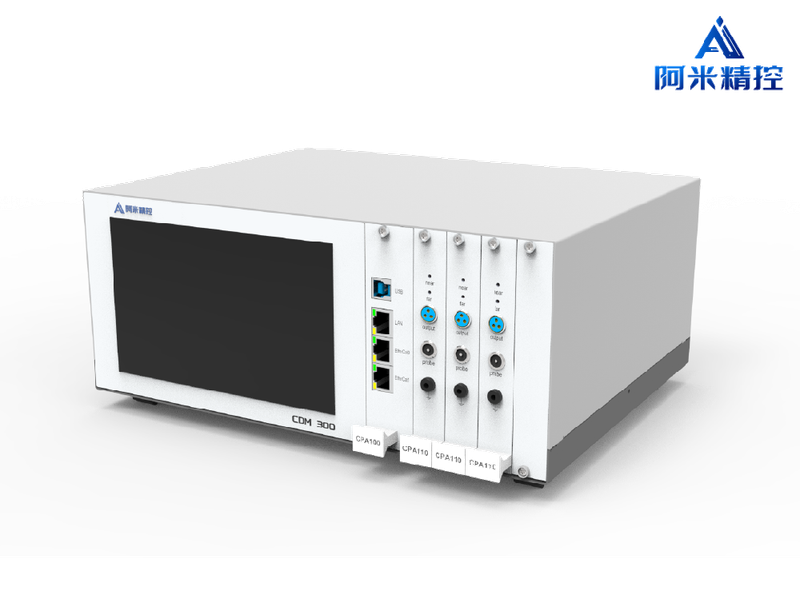 Three Channel Sensor Main Unit CDM-300 CDM300 + Preamplifier CPA110
Sensors
Attomotion
Fits the detectives.: PC06-100/ PC10-200/ PC20-2000 Channels: 3 Output: Simulation : Adjustable , Default ±5V Difference ; Communications : USB, Ethernet, EtherCAT, CAN, RS232 Real time : SPI
•CDM-300 Controller CDM-300 Microshift Sensor Main Unit Special Compact Application Design , Internal Preamplifier 、 Filters and signal adjust circuits , And for the right spot. Drive Optimization , Fit for integrated application 。 Here. Multichannel Controller It's the core. Capacitive Microdisplacement Sensor Super-precision measurement applications for high-requirement indicators 。 Embedding different working patterns to adapt to measurements based on static indicators and to the measurement of the measurement of the measurement of the measurement of the measurement of the measurement of the measurement of the measurement of the measurement of the measurement of the measurement of the measurement of the measurement of the measurement of the measurement of the measurement of the measurement of the measurement of the measurement of the measurement of the measurement of the measurement of the measurement of the measurement of the measurement of the measurement of the measurement of the measurement of the measurement of the measurement of the use of the measurement of the measurement of the use of the measurement of the measurement of the measurement of the measurement of the measurement of the measurement of the measurement of the use of the measurement of the measurement of the use of the use of the measurement of the measurement of the measurement of the measurement of the use of the measurement of the measurement of the measurement of the measurement of the use of the use of the use of the use of the use of the use of the measurement of the measurement of the measurement of the measurement of the measurement of the measurement of the measurement of the measurement of the use of the measurement of the static indicators of the measurement of the use of the use of the use of the use of the use of the use of the use of the use of the use of the use of the use of the use of the use of the use of the use of the use of the use of the measurement of the Dynamic Indicator-based real-time applications , And balance. Dynamic and static indicators for high bandwidth super-precision feedback control systems 。 Multichannel Controller Inline Channel Synchronization , Support 3 Synchronization of the channel , For thickness detection 、 Rotation bias correction etc. 。
-
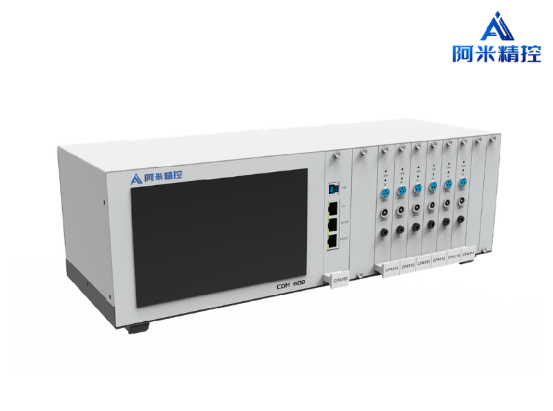 Six Channel Sensor Main Unit CDM-600 CDM600
Sensors
Attomotion
Fits the detectives.: PC06-100/ PC10-200/ PC20-2000 Channels: 6 Output: Communications : USB, Ethernet, EtherCAT, CAN, RS232 Real time : SPI
CDM-600 Controller CDM-600 Six Channel Microshift Sensor Main Unit Special Compact Application Design , Internal Preamplifier 、 Filters and signal adjust circuits , And for the right spot. Drive Optimization , Fit for integrated application 。 Here. Multichannel Controller It's the core. Capacitive Microdisplacement Sensor Super-precision measurement applications for high-requirement indicators 。 Embedding different working patterns to adapt to measurements based on static indicators and to the measurement of the measurement of the measurement of the measurement of the measurement of the measurement of the measurement of the measurement of the measurement of the measurement of the measurement of the measurement of the measurement of the measurement of the measurement of the measurement of the measurement of the measurement of the measurement of the measurement of the measurement of the measurement of the measurement of the measurement of the measurement of the measurement of the measurement of the measurement of the measurement of the measurement of the use of the measurement of the measurement of the use of the measurement of the measurement of the measurement of the measurement of the measurement of the measurement of the measurement of the use of the measurement of the measurement of the use of the use of the measurement of the measurement of the measurement of the measurement of the use of the measurement of the measurement of the measurement of the measurement of the use of the use of the use of the use of the use of the use of the measurement of the measurement of the measurement of the measurement of the measurement of the measurement of the measurement of the measurement of the use of the measurement of the static indicators of the measurement of the use of the use of the use of the use of the use of the use of the use of the use of the use of the use of the use of the use of the use of the use of the use of the use of the use of the measurement of the Dynamic Indicator-based real-time applications , And balance. Dynamic and static indicators for high bandwidth super-precision feedback control systems 。 Multichannel Controller Inline Channel Synchronization , Most supported 6 Synchronization of the channel , For thickness detection 、 Rotation bias correction etc. 。
Related Articles
As a professional ultraviolet‑laser solution provider, Precilasers has launched its 266 nm narrow‑linewidth industrial laser, delivering reliable single‑frequency output for high‑precision interference lithography, semiconductor inspection and precision metrology applications.
On November 28, 2024, the 3rd China Laser Star Enterprise Summit & Advanced Laser Processing Technology Summit, an annual influential event in the laser industry, was grandly held in Wuhan Optics Valley.
Within cutting‑edge ultrafast photonics research, asynchronous optical sampling (ASOPS) and synchronous sampling serve as fundamental technologies for terahertz excitation detection, coherent Raman imaging and other time‑resolved spectroscopy experiments.
A laser bar is an array semiconductor laser chip integrated with dozens of emitters, which realizes hundred-watt quasi-continuous output on a single chip. With regular emitter arrangement and controllable fill factor, integrated thermal design and superior wall-plug efficiency compared to single chips, it acts as the core light source for high-power pumping, medical lasers and precision processing.
Loading...
Name
Phone
Organization
Use Case

Database Platform