

RF Driver 97-02925-32
97-02925-32 is a high-performance RF driver operating over20–160 MHz and supplying up to0.44 W RF output into50 Ω, with analog and digital modulation. Designed for AODs and AOTFs, it provides stable, precise RF drive signals for laser scanning, multispectral imaging, spectral analysis, laser processing, and research. Good frequency stability and modulation performance support precision beam control and fast wavelength switching. Compatible devices: acousto-optic deflectors and tunable filters. Technical notes: actual frequency resolution is0.0931 Hz; the system automatically selects the nearest output frequency. Frequency preload time is typically1~10 μs. Each frequency datum comprises a32-bit frequency-control word and its starting RAM address. It supports3 preloaded frequencies and switches between the three presets in less than20 ns. Nominal0.4 W output is obtained at maximum RF gain. RF gain is linearly adjustable over30 dB, maintaining constant signal-to-noise ratio throughout. Modulation bandwidth is measured at the-3 dB point with DC coupling. Dynamic range is defined over20~160 MHz from the1 dB compression point to the minimum attainable output. Intermodulation is measured using two tones at100 MHz and105 MHz, each at125 mW. Signal-to-noise ratio is measured in1 MHz bandwidth, referenced to a125 mW output signal.
 Save to Favorites
Overview
Specifications
| Parameter | Value |
|---|---|
| Operating Frequency | 20–160 MHz |
| Frequency Resolution [Actual0.0931Hz; Select the Frequency Nearest the Target (Note1)] | 0.1 Hz |
| Frequency Stability | ±2 ppm/℃ |
| Frequency Preload Time [Typically1–10μs;32-Bit Frequency Control Word and Starting RAM Address (Note2)] | <10 μs |
| Frequency Switching Time [Switching between Three Preloaded Frequencies (Note3)] | <20 ns |
| RF Output Power [Output Gain at Maximum; Nominal Value (Note4);50Ω Load] | 0.4 W |
| RF Output Gain Adjustment Range [Linear Adjustment; Constant Signal-to-Noise Ratio across the Range (Note5)] | 30 dB |
| Modulation Bandwidth [-3dB test point; DC coupling (Note 6)] | >2 MHz |
| Dynamic Range [20–160MHz; From1dB Compression Point to Minimum Attainable Power (Note7)] | >40 dBc |
| Intermodulation Suppression [Two Tones100/105MHz;125mW per Tone (Note8)] | >40 dB |
| Spurious Suppression | >30 dBc |
| Signal-to-Noise Ratio [1MHz Measurement Bandwidth;125mW Reference Signal (Note9)] | >90 dB |
| Output Impedance | 50 Ω |
| Amplitude Modulation Input Level | 0~10 V |
| FSK Modulation Input Level | 3.3 V |
| Blanking Input Level | 3.3 V |
| Digital Control Interface | ASCII Command Set |
| Sensor Input | ±3.3 V |
| Power Input | 12 VDC,1 A |
Key Features
Datasheet
Please provide your email to download the datasheet.
Invalid email format. Please try again.
Supplier Information
Related Products
-
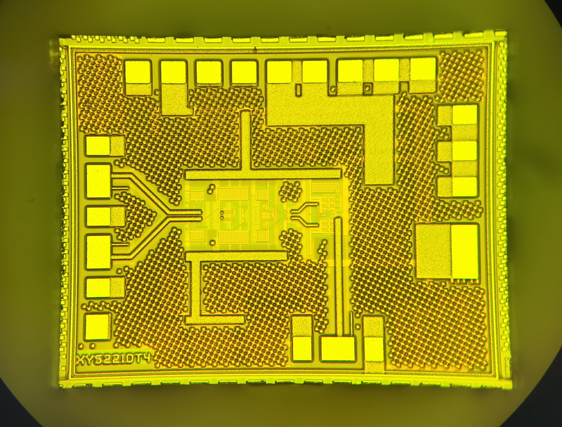 1CH×25G/28G DML Driver
Software and Data Services
Xy-technology
XY5221DD is One. Single Channel Laser Driver , Designed for direct modems 25Gb/s Laser Interface 。 The currents and the transients can be replaced by the currents. 2 Line Line Lines Interface Independent Programming , Meanwhile... 2 Line Interface Supports also the inclusion of programmability for balancing and cross-point adjustments , Take one. Tx Disable , It can be closed. Laser Erosion and Moderation Current , Existing IBIAS Monitor 。 This simulation output can be used to Laser Overcrowding and / or Laser Modulation Current for External Monitoring 。 There's a piece in there. ADC Functions , It can be used for foot-inducing measurements via electrical input of a special back-cover monitor TX_PWR。ADC It can also be configured for measurement. VCC( ..can measure each Power Supply ) and IBIAS( Average Laser Erosion of currents )。
-
1CH×25G/28G EML Driver
Software and Data Services
Xy-technology
XY5221E is A high-performance piece. Single Channel 28Gbps EML Driver 。 It provides daring. 30GHz High bandwidth and greater than 2.5Vpp and the output range , The cost of the operation is about 0.17W。 It's designed for use in... Drive EML Laser , The chip is available in nudity chip form. 。
-
 4CH×25G/28G DML Driver
Software and Data Services
Xy-technology
XY5224DD is One. Four Channel Laser Driver , Designed for direct modems 25Gb/s Laser Interface 。 The currents and the transients can be replaced by the currents. 2 Line Line Lines Interface Independent Programming , Meanwhile... 2 Line Interface Supports also the inclusion of programmability for balancing and cross-point adjustments , Take one. Tx Disable , It can be closed. Laser Erosion and Moderation Current , Existing IBIAS Monitor 。 This simulation output can be used to Laser Overcrowding and / or Laser Modulation Current for External Monitoring 。 There's a piece in there. ADC Functions , It can be used for foot-inducing measurements via electrical input of a special back-cover monitor TX_PWR。ADC It can also be configured for measurement. VCC( ..can measure each Power Supply ) and IBIAS( Average Laser Erosion of currents )。
-
4CH×25G/28G EML Driver
Software and Data Services
Xy-technology
XY5224E is A high-performance piece. Four Channel 28Gbps EML Driver 。 It provides daring. 30GHz High bandwidth and greater than 2.5Vpp and the output range , The cost of the operation is about 0.45W。 It's designed for use in... Drive EML Laser , The chip is available in nudity chip form. 。
-
 25G/28G CDR+VCSEL Driver
Software and Data Services
Xy-technology
XY5921V Integration VCSEL Driver 、 Balancer and clock data recovery 。 None The reference clock will support it. 24.3Gbps Present. 28.1Gbps Rate range , It's also possible. bypass Mode supports lower rate 。 The chip is provided in nudist form. 。
Related Articles
As a professional ultraviolet‑laser solution provider, Precilasers has launched its 266 nm narrow‑linewidth industrial laser, delivering reliable single‑frequency output for high‑precision interference lithography, semiconductor inspection and precision metrology applications.
On November 28, 2024, the 3rd China Laser Star Enterprise Summit & Advanced Laser Processing Technology Summit, an annual influential event in the laser industry, was grandly held in Wuhan Optics Valley.
Within cutting‑edge ultrafast photonics research, asynchronous optical sampling (ASOPS) and synchronous sampling serve as fundamental technologies for terahertz excitation detection, coherent Raman imaging and other time‑resolved spectroscopy experiments.
A laser bar is an array semiconductor laser chip integrated with dozens of emitters, which realizes hundred-watt quasi-continuous output on a single chip. With regular emitter arrangement and controllable fill factor, integrated thermal design and superior wall-plug efficiency compared to single chips, it acts as the core light source for high-power pumping, medical lasers and precision processing.
Loading...
Name
Phone
Organization
Use Case

Database Platform