
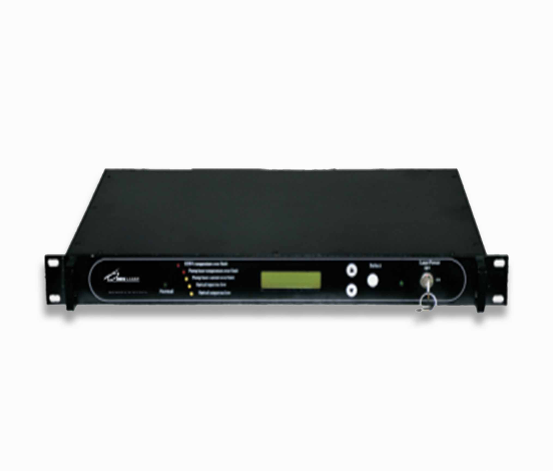
17dBm Polarization Maintaining Fiber Amplifier Aack
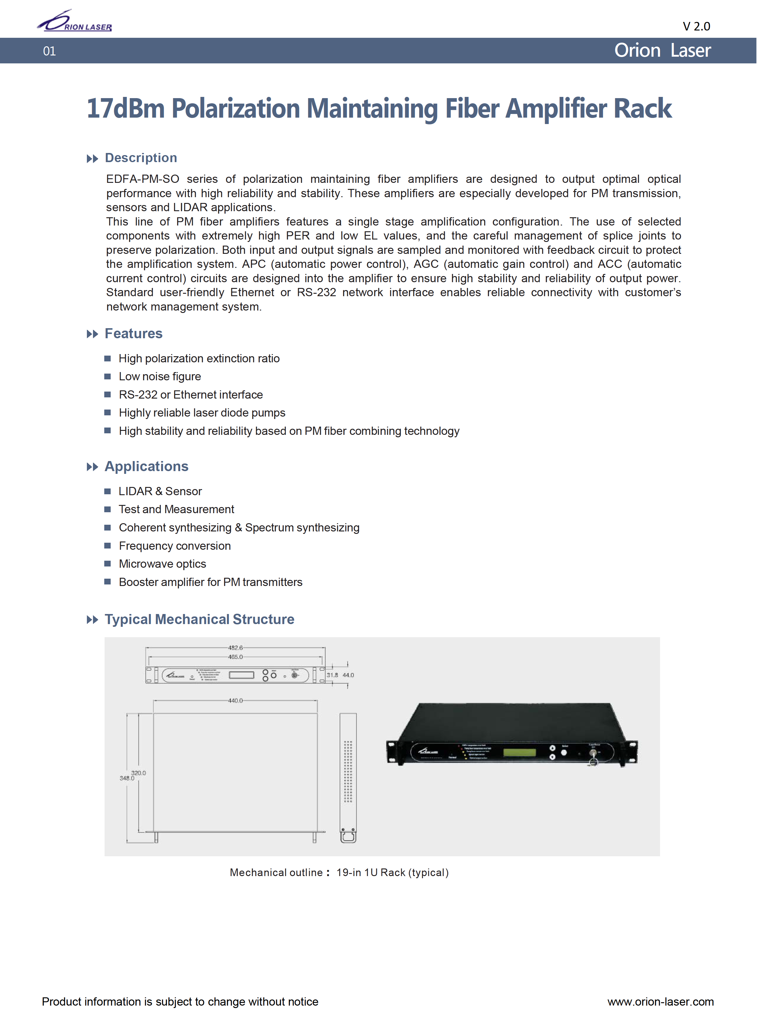
EDFA-PM-SO series of polarization maintaining fiber amplifiers are designed to output optimal optical performance with high reliability and stability. These amplifiers are especially developed for PM transmission, sensors and LIDAR applications. This line of PM fiber amplifiers features a single stage amplification configuration. The use of selected components with extremely high PER and low EL values, and the careful management of splice joints to preserve polarization. Both input and output signals are sampled and monitored with feedback circuit to protect the amplification system. APC (automatic power control), AGC (automatic gain control) and ACC (automatic current control) circuits are designed into the amplifier to ensure high stability and reliability of output power. Standard user-friendly Ethernet or RS-232 network interface enables reliable connectivity with customer’s network management system.
 Save to Favorites
Overview
Specifications
| Parameter | Value |
|---|---|
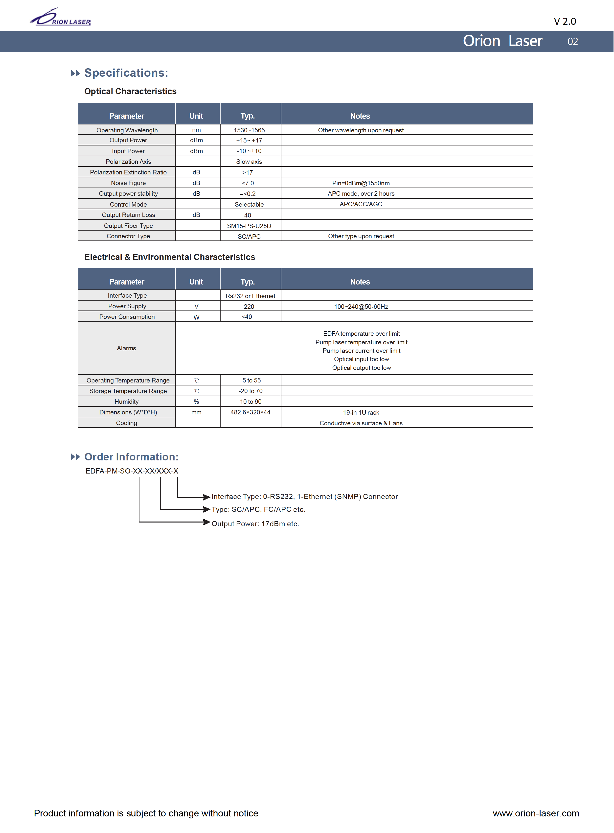
| Operating Wavelength [Other wavelength upon request] | Typical :1530~1565 nm |
| Output Power | Typical :+15~+17 dBm |
| Input Power | Typical :-10~+10 dBm |
| Polarization Axis | Typical :Slow axis |
| Polarization Extinction Ratio | Typical :>17 dB |
| Noise Figure [Pin=0dBm@1550nm] | Typical :<7.0 dB |
| Output power stability [APC mode, over 2 hours] | Typical :=<0.2 |
| Control Mode [APC/ACC/AGC] | Typical :Selectable |
| Output Return Loss | Typical :40 dB |
| Output Fiber Type | Typical :SM15-PS-U25D |
| Connector Type [Other type upon request] | Typical :SC/APC |
| Interface Type | Typical :Rs232 or Ethernet |
| Power Supply [100~240@50-60Hz] | Typical :220 V |
| Power Consumption | Typical :<40 W |
| Operating Temperature Range | Typical :-5 to 55 ℃ |
| Storage Temperature Range | Typical :-20 to 70 ℃ |
| Humidity | Typical :10 to 90 % |
| Dimensions (W*D*H) [19-in 1U rack] | Typical :482.6 mm × 320 mm × 44 mm |
| Alarms | EDFA temperature over limit;Pump laser temperature over limit;Pump laser current over limit;Optical input too low;Optical output too low |
| Cooling | Conductive via surface & Fans |
Applications
Key Features
Datasheet
Please provide your email to download the datasheet.
Invalid email format. Please try again.
Supplier Information
Related Products
-
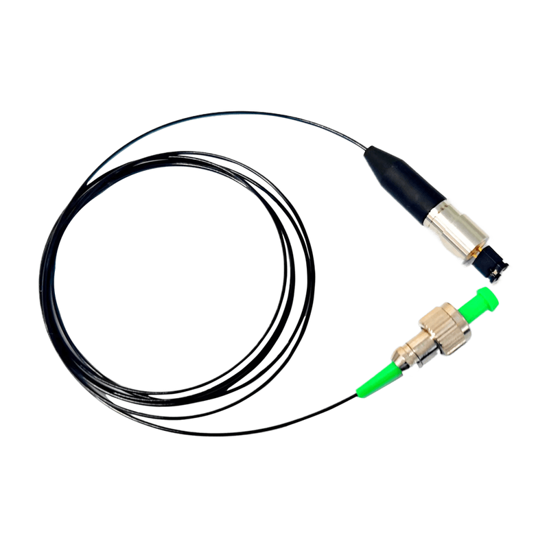 Single-Mode Polarization-Maintaining Fiber-Coupled Laser BGFL-405-PM-FP-80
Polarization Maintaining Products
Bogaolaser
Center wavelength λc [25℃]: min:400 nm;typical:405 nm;max:410 nm Continuous Output Power Po [25℃]: typical:80 mW Spectral width △λ [25℃]: typical:2.0 nm
Single-mode polarization-maintaining fiber-coupled lasers with wavelengths of 375-1550nm and wavelength-dependent customizable power. Coaxial packages are available throughout. Fiber core diameters: 3.0um, 3.5um, 4.0um, 5.0um, 5.5um and 6.5um; connector options: SMA905, FC and ST; external dimensions (φ8φ10φ12mm) can be customized.
-
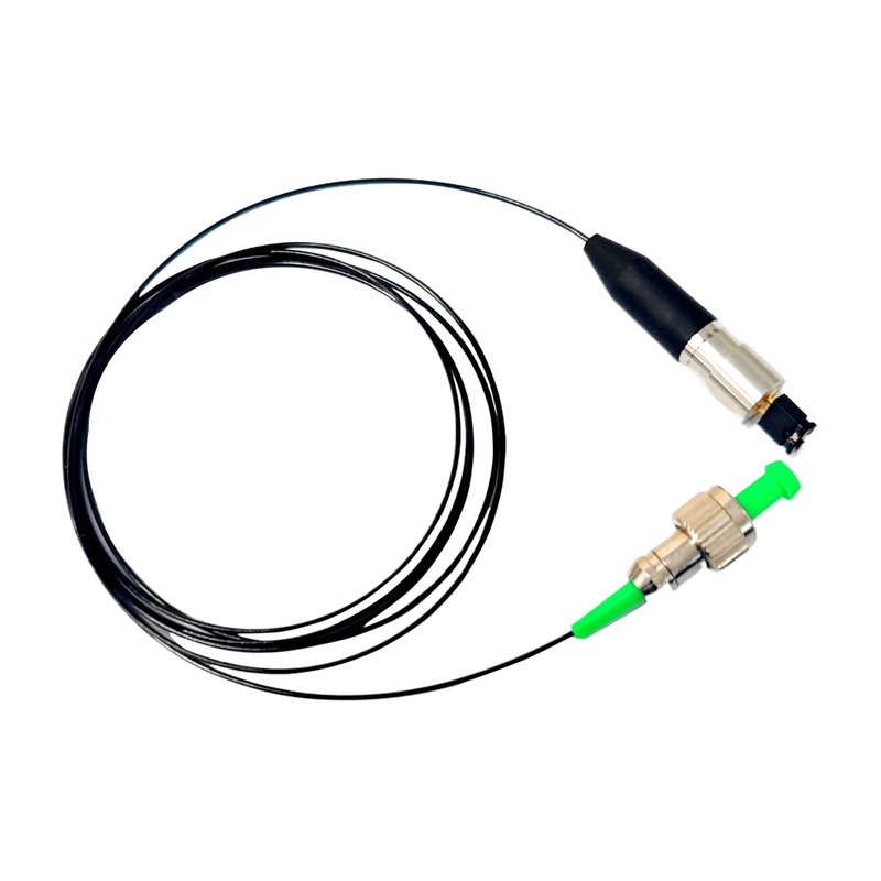 Single-Mode Polarization-Maintaining Fiber-Coupled Laser BGFL-450-PM-FP-50
Polarization Maintaining Products
Bogaolaser
Center wavelength λc [25℃]: min:445 nm;typical:450 nm;max:455 nm Continuous Output Power Po [25℃]: typical:50 mW Spectral width △λ [25℃]: typical:2.0 nm
Single-mode polarization-maintaining fiber-coupled lasers with wavelengths of 375-1550nm and wavelength-dependent customizable power. Coaxial packages are available throughout. Fiber core diameters: 3.0um, 3.5um, 4.0um, 5.0um, 5.5um and 6.5um; connector options: SMA905, FC and ST; external dimensions (φ8φ10φ12mm) can be customized.
-
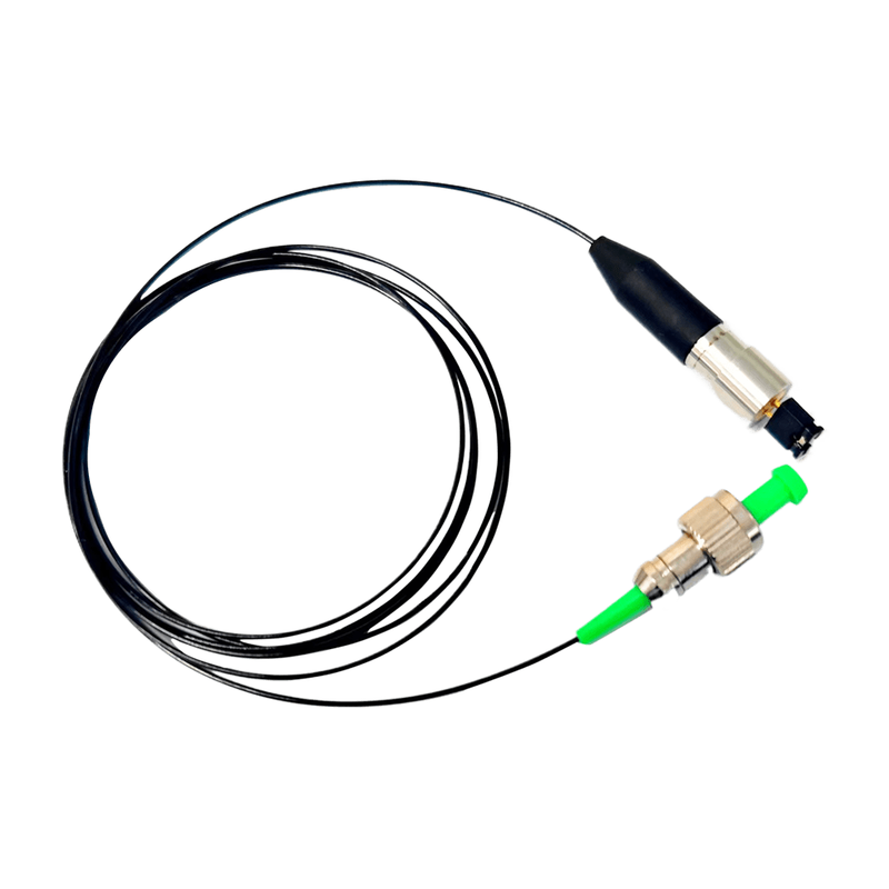 Single-Mode Polarization-Maintaining Fiber-Coupled Laser BGFL-488-PM-FP-40
Polarization Maintaining Products
Bogaolaser
Center wavelength λc [25℃]: min:485 nm;typical:488 nm;max:491 nm Continuous Output Power Po [25℃]: typical:40 mW Spectral width △λ [25℃]: typical:2.0 nm
Single-mode polarization-maintaining fiber-coupled lasers with wavelengths of 375-1550nm and wavelength-dependent customizable power. Coaxial packages are available throughout. Fiber core diameters: 3.0um, 3.5um, 4.0um, 5.0um, 5.5um and 6.5um; connector options: SMA905, FC and ST; external dimensions (φ8φ10φ12mm) can be customized.
-
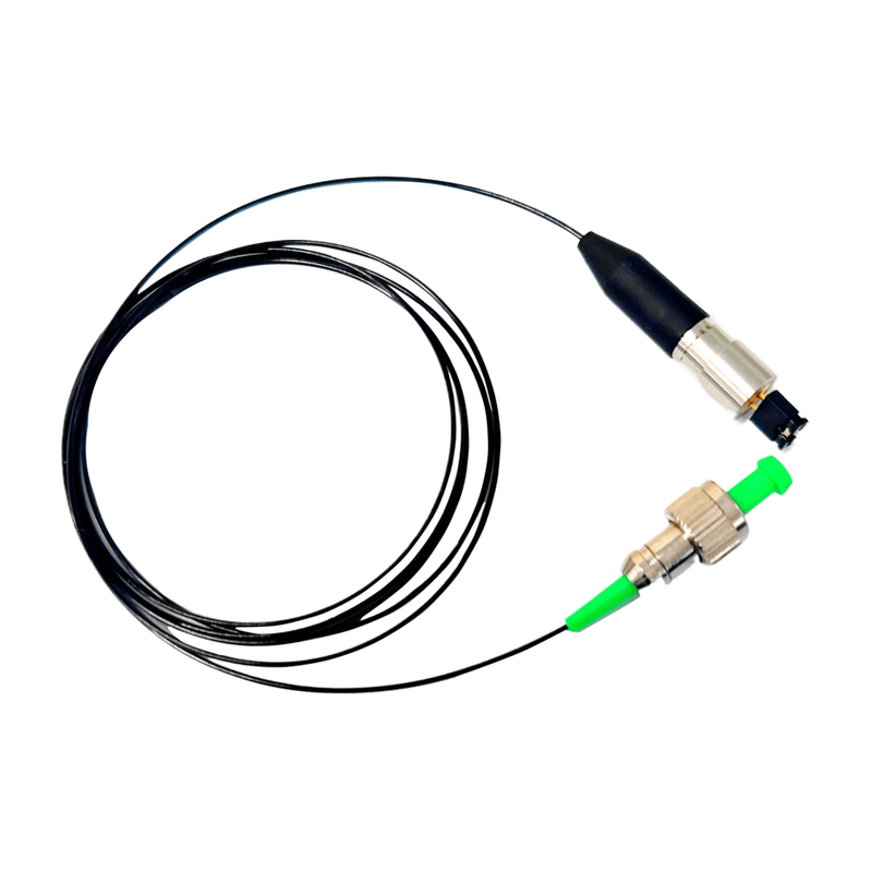 Single-Mode Polarization-Maintaining Fiber-Coupled Laser BGFL-505-PM-FP-40
Polarization Maintaining Products
Bogaolaser
Center wavelength λc [25℃]: min:500 nm;typical:505 nm;max:510 nm Continuous Output Power Po [25℃]: typical:40 mW Spectral width △λ [25℃]: typical:2.0 nm
Single-mode polarization-maintaining fiber-coupled lasers with wavelengths of 375-1550nm and wavelength-dependent customizable power. Coaxial packages are available throughout. Fiber core diameters: 3.0um, 3.5um, 4.0um, 5.0um, 5.5um and 6.5um; connector options: SMA905, FC and ST; external dimensions (φ8φ10φ12mm) can be customized.
-
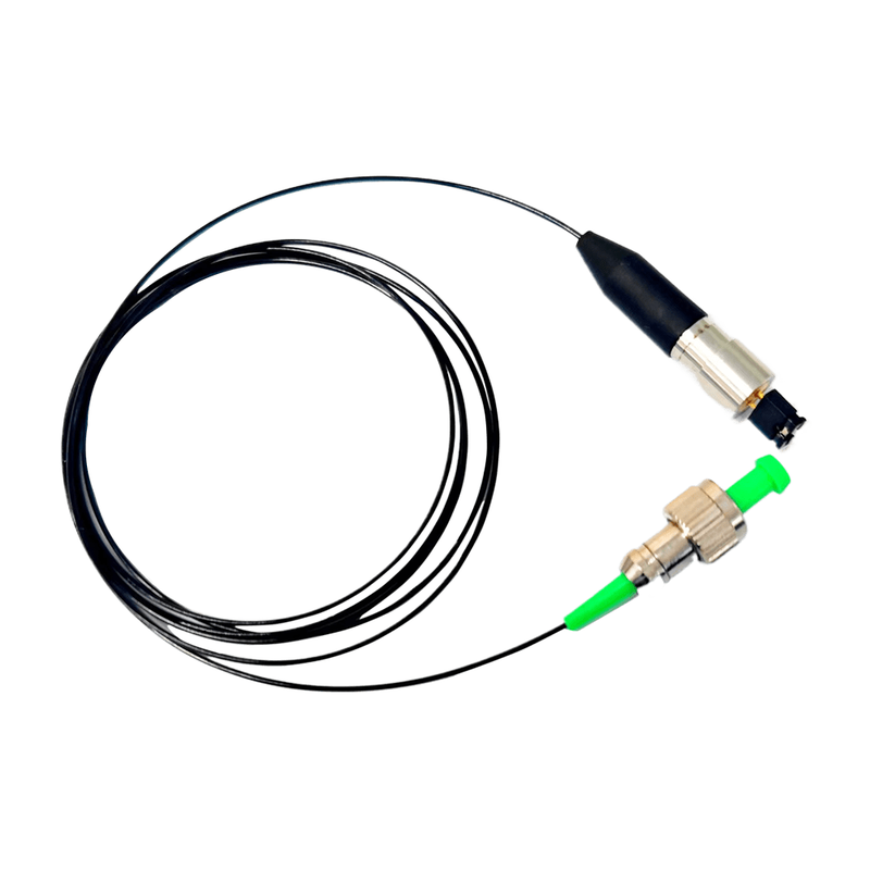 Single-Mode Polarization-Maintaining Fiber-Coupled Laser BGFL-520-PM-FP-40
Polarization Maintaining Products
Bogaolaser
Center wavelength λc [25℃]: min:516 nm;typical:520 nm;max:522 nm Continuous Output Power Po [25℃]: typical:40 mW Spectral width △λ [25℃]: typical:2.0 nm
Single-mode polarization-maintaining fiber-coupled lasers with wavelengths of 375-1550nm and wavelength-dependent customizable power. Coaxial packages are available throughout. Fiber core diameters: 3.0um, 3.5um, 4.0um, 5.0um, 5.5um and 6.5um; connector options: SMA905, FC and ST; external dimensions (φ8φ10φ12mm) can be customized.
Related Articles
A laser bar is an array semiconductor laser chip integrated with dozens of emitters, which realizes hundred-watt quasi-continuous output on a single chip. With regular emitter arrangement and controllable fill factor, integrated thermal design and superior wall-plug efficiency compared to single chips, it acts as the core light source for high-power pumping, medical lasers and precision processing.
FiDAR, the fiber‑optic radar vehicle positioning and tracking system developed by Jianhe Bafang, is a high‑sensitivity distributed fiber‑sensing solution designed for intelligent traffic road monitoring. It outputs real‑time spatial coordinates of every vehicle across the full road section around‑the‑clock, delivering a brand‑new sensing technology for vehicle‑road cooperation, smart highway construction and urban traffic management.
As premium broadband light sources situated between traditional LEDs and laser diodes, MicroLight superluminescent‑diode (SLD) products combine broad spectral bandwidth, sufficient optical output power and low‑coherence performance.
Precise spectral screening is essential for high-precision medical detection, spectroscopic analysis and intelligent imaging systems. Tailored for visible and near-infrared spectral separation, the SP900 shortpass optical filter delivers high-efficiency light transmission and deep infrared blocking performance. It effectively eliminates stray light interference, improves signal-to-noise ratio (SNR), and serves as a core optical component for biomedical instruments, scientific analysis equipment and machine vision systems.
Loading...
Name
Phone
Organization
Use Case

Database Platform