
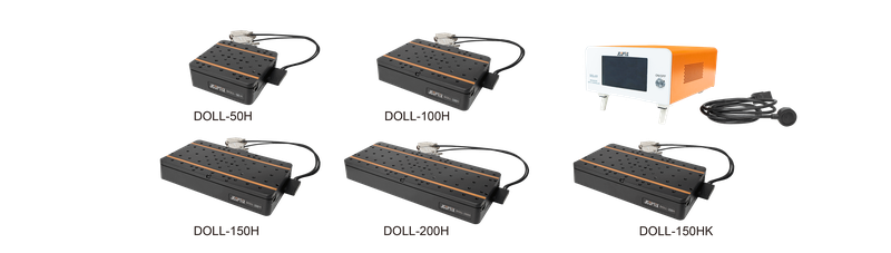
High-Precision Linear Motor Translation Stage DOLL-100HK
JCOPTIX high-precision direct-drive linear-motor stages have Jiangsu metrology-institute testing/certification reports. A traveling magnetic field applies electromagnetic thrust directly without complex transmission components or friction, enabling high speed/acceleration. Eliminating screw backlash and long-term wear maintains accuracy. Linear motors suit demanding positioning, running smoothly even at the lowest speeds and without vibration at high speed, avoiding nonlinear control behavior and allowing easy control at every position. Highly linear force can be freely set/strictly controlled. High-value DOLL stages combine direct drive, crossed rollers, and precision optical feedback for excellent dynamics/accuracy. They operate independently or combine through existing holes into complex multiaxis systems. DOLL travels 50~200 mm, load 100 N, maximum speed 500 mm/s, unloaded acceleration 15 m/s². Responsive drive/fine-pitch scales provide 100 nm minimum increments. Precision microassembly, AOI, microscopy, and micro/nanoprocessing in semiconductor, LCD, microelectronics, and biomedical fields benefit from efficient stable intelligent operation. Higher-accuracy/flexible complete systems are customizable. Precision linear-motor stages, travel 50~200 mm. Models: DOLL-50H, DOLL-100H, DOLL-150H, DOLL-200H. Effective travels 50, 100, 150, 200 mm; blackened aluminum alloy; direct drive without backlash; full-closed-loop scale feedback, nanometer precision, minimum 100 nm. JCOPTIX DOLL direct-drive stages offer 50, 100, 150, 200 mm travel with crossed rollers and precision optical feedback. High dynamics/accuracy support single axes or multiaxis combinations through mounting holes. Load 100 N, maximum 500 mm/s, unloaded acceleration 15 m/s², responsive drive/fine scales provide 100 nm increments. DOLL requires DCL-01 precision servo controllers. Precision linear-motor kits, travel 50-200 mm. Models: DOLL-50HK, DOLL-100HK, DOLL-150HK, DOLL-200HK. Effective travels 50, 100, 150, 200 mm; blackened aluminum alloy; full-closed-loop scales, nanometer precision, minimum 100 nm; controller/power included. JCOPTIX DOLL direct-drive stages offer 50, 100, 150, 200 mm travel, crossed rollers, and precision optical feedback for high dynamics/accuracy. Single-axis use or multiaxis systems through mounting holes are supported. Load is 100 N, maximum speed 500 mm/s, unloaded acceleration 15 m/s², and responsive drive/fine scales provide 100 nm steps. Included DCL-01 servo controllers and power supplies allow immediate use. Core-parameter test methods: equipment indicators and DOLL examples retained separately. Stage core parameters. In precision manufacturing, semiconductors, optoelectronic inspection, and research, motion accuracy, stability, and reliability determine quality/efficiency. Test methods/standards define device quality; pitch, yaw, positioning accuracy, and repeatability quantify motion errors. Jiangsu metrology results: JCOPTIX commissioned the Jiangsu Institute of Metrology to test/report stage parameters under 1251-2010, Calibration Specification for Coordinate Positioning Measurement Systems. API XD Laser 6D interferometry measures positioning, pitch/yaw, and other parameters in one setup at 0.5ppm accuracy. Figure 1. Jiangsu institute's stage test report. JCOPTIX test methods: GB/T 11336-2004 procedures use Renishaw XL-80 interferometers and Nuoxu NORMAT1210 precision photoelectric autocollimators. Nuoxu NORMAT1210 measures pitch/yaw over ±1000 arcsec with ±1 arcsec accuracy and 0.2 arcsec repeatability, capturing tiny angular deviations/wobble across a 3800 arcsec × 2800 arcsec field. Segmented measurements and accumulated calculations determine actual-versus-ideal trajectory deviations. Optical accumulation improves accuracy; software directly outputs angles, usually arcseconds or microradians, with lower overall error. 1. Pitch/yaw. (1). Pitch: tabletop rotation θX about the horizontal X axis perpendicular to travel. (2). Yaw: θZ about the vertical Z axis. Figure 2. Pitch/yaw test schematic. 2. Repeatability/positioning accuracy. (1). Positioning accuracy is maximum error from the reference origin to target points over full travel, a key performance indicator. (2). Repeatability usually refers to repeated bidirectional positioning, such as ±X, and actual-versus-set position error over repeated arrivals at one command position, reflecting stability/consistency. Under GB/T 17421.2-2023, JCOPTIX uses Germany's Renishaw XL-80 with multiple target points and repeated forward/reverse arrivals. Actual positions and maximum deviations at each target calculate both repeatability and positioning accuracy. Accuracy is ±0.5 ppm, resolution 1 nm, and stable operation 0-40℃. Environmental compensation corrects temperature, pressure, and humidity, while up to 50 kHz dynamic acquisition captures small motion errors. Figure 3. Interferometric positioning test of precision direct-drive stages. 3. Speed stability. Actual speed fluctuation at a set speed reflects smoothness of control. Renishaw XL-80 dynamic acquisition at 50 kHz records displacement/time during commanded constant-speed travel; software derives speed/fluctuation. For example, JCOPTIX DOLL products over 50~200 mm travel reach 500 mm/s maximum and unloaded acceleration 15 m/s². 4. Homing accuracy. Deviation between the returned and original zero after motion reflects origin stability. Renishaw XL-80 records the initial zero and actual zero after repeated full-travel cycles; maximum deviation is homing accuracy. 5. Minimum achievable and repeatable increments. (1). Minimum achievable increment characterizes the smallest motion step. Renishaw XL-80 measures each actual increment during repeated commanded minimum steps to confirm the achievable minimum. (2). Minimum repeatable increment is the smallest physical step with stable repeatable response, statistically verified and normally no smaller than design resolution. Under GB/T 17421.2-2023, select a random 40 μm segment within full travel, step at the proposed minimum, for example 4 μm, use a 5 μm jump, and repeat 5 cycles. Measured repeatability must be below 20% of the increment, for example 4 μm × 20% = 0.8 μm. Every JCOPTIX motorized stage is tested to relevant standards before delivery and includes a shipment test report.
 Save to Favorites
Overview
Specifications
| Parameter | Value |
|---|---|
| Motor type | Linear Motor |
| Effective Travel | 100 mm |
| Positioning Accuracy | ± 2.5 μm |
| Pitch | ± 75 μrad |
| Yaw | ± 75 μrad |
| Straightness | ± 2 μm |
| Flatness | ± 2 μm |
| Minimum Incremental Motion | 100 nm |
| Maximum Speed | 500 mm/s |
| Weight | 3.5 kg |
| Translation Stage Material | Blackened Aluminum Alloy |
| Mean Time Between Failures | 20000 h |
| Maximum Acceleration | 15 m/s²(No Load) |
| Max continuous force | 19 N |
| Controller and Power Supply | Present |
| Maximum Centered Load Capacity | 100 N |
| Sensor Type | Absolute Sensor |
| Repeatability | ± 0.2 μm |
| Design Resolution | 50 nm |
| Platform mounting hole specification | M4 and M6 |
Key Features
Datasheet
Supplier Information
Related Products
-
 PG6030-20HGJL
Motors and Drives
Chinaddwy
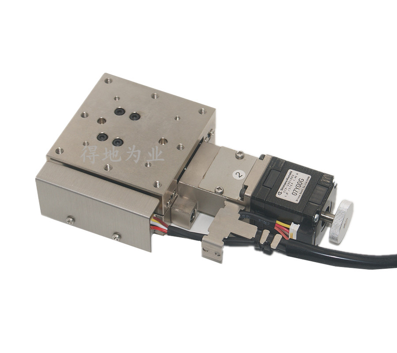
Platform Dimensions: 60 mm × 60 mm × 20 mm Travel: ±15 mm Lead screw type: Ball Screw
Standard stepper motor and RS232 for controller connection; selectable precision ball screw or thread-ground leadscrew for good repeatability and absolute accuracy, low axial clearance, and long life; anti-loosening and anti-axial-shift construction for accuracy during fast reciprocation; integrated ball guides for smooth motion without fastening bolts, enabling a thin design; precision base and guide mounting reduce pitch/yaw and improve straightness/parallelism; a flexible motor/screw coupling reduces eccentric disturbance and noise; handwheel for setup; zero and limit switches; standard-spaced threaded and through base holes. 10. Optional servo motor and linear grating scale for closed-loop control; modifications and customization available.
-
 XXY-100
Motors and Drives
Chinaddwy
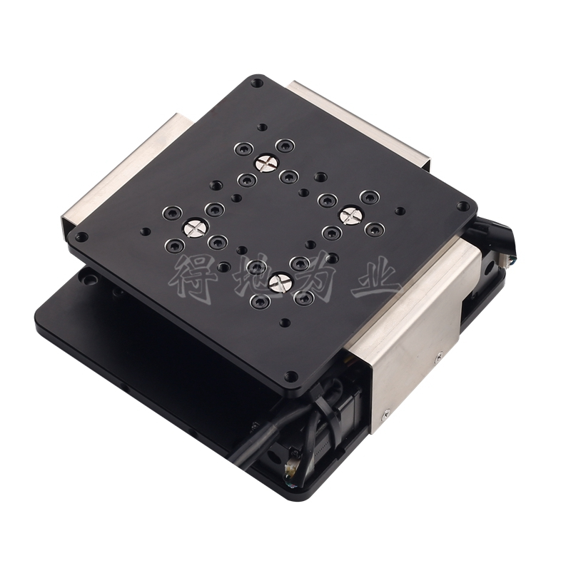
Platform Dimensions: 100 mm × 100 mm XY-axis travel: ±5×±5 Ball Screw Diameter: Φ6
Standard stepper motor and RS232; compact, thin, lightweight construction for light loads, low speeds, and scientific experiments; a precision-ground small-lead screw for high resolution at the same microstepping factor; an antibacklash nut minimizing screw-pair clearance; crossed-ball guides for smooth travel with lateral preload adjustment and clearance elimination; a high-quality flexible motor/ball-screw coupling for synchronous transmission, reduced eccentric disturbance, and low noise; zero and limit switches for positioning and protection; standard-spaced threaded and through base holes.
-
 XXY-160
Motors and Drives
Chinaddwy
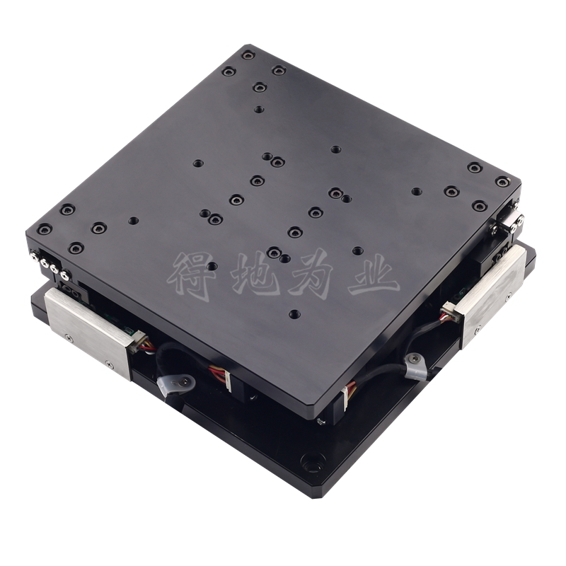
Platform Dimensions: 160 mm × 160 mm XY-axis travel: ±5×±5 Ball Screw Diameter: Φ6
Standard stepper motor and RS232; compact, thin, lightweight construction for light loads, low speeds, and scientific experiments; a precision-ground small-lead screw for high resolution at the same microstepping factor; an antibacklash nut minimizing screw-pair clearance; crossed-ball guides for smooth travel with lateral preload adjustment and clearance elimination; a high-quality flexible motor/ball-screw coupling for synchronous transmission, reduced eccentric disturbance, and low noise; zero and limit switches for positioning and protection; standard-spaced threaded and through base holes.
-
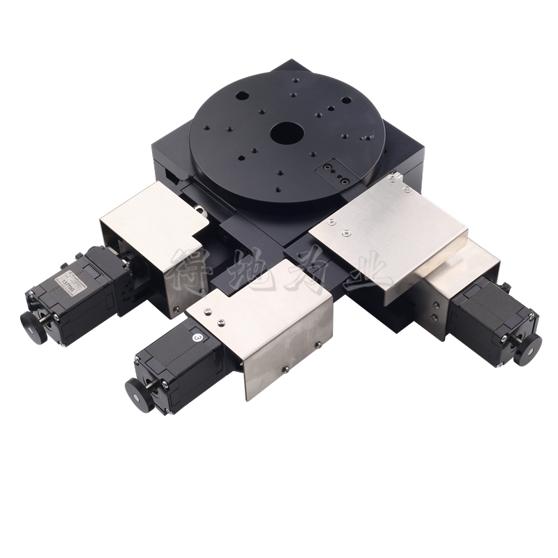 XYR-120L
Motors and Drives
Chinaddwy
Platform Dimensions: Φ120 Travel [X/Y axes; No ± added]: 30 mm Travel [R Axis]: ±10 °
Standard stepper motor and RS232; compact, thin, lightweight construction for light loads, low speeds, and scientific experiments; a precision-ground small-lead screw for high resolution at the same microstepping factor; an antibacklash nut minimizing screw-pair clearance; integrated three-axis construction; crossed-ball guides with lateral preload adjustment and clearance elimination, supporting multidimensional combinations; precision base and guide mounting reduce pitch/yaw and improve straightness/parallelism; a flexible motor/ball-screw coupling for synchronized transmission with reduced eccentric disturbance and noise; a handwheel for setup. 10. Zero and limit switches for positioning and protection. 11. Standard-spaced threaded and through base holes. 12. Optional servo motor and linear grating scale for closed-loop control; modifications and customization available.
-
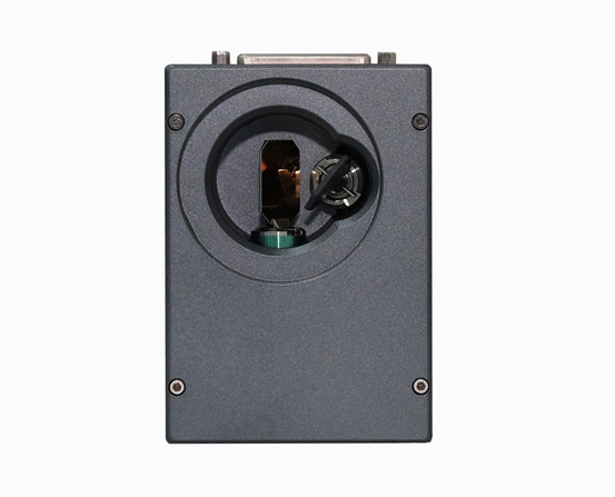 10 mini two-dimensional scanning system
Motors and Drives
Sp-scan
Incident beam spot: 10 mm Following error time: 170 us Marking Speed [F-theta f=160mm]: 1.5 m/s
The MINI version reduces the size of standard products for benchtop marking, portable marking, and automation integration.
Related Articles
Founded in 2003, BWT Beijing Optoelectronics adheres to the mission "Let Dreams Fly With Light" and vision of becoming a Global Leader in Laser Solutions, guided by the core value "Innovate to Achieve Extraordinary".
As premium broadband light sources situated between traditional LEDs and laser diodes, MicroLight superluminescent‑diode (SLD) products combine broad spectral bandwidth, sufficient optical output power and low‑coherence performance.
Founded in November 2017, TIANJIN H‑CHIP TECHNOLOGY GROUP CORPORATION is a professional manufacturing‑service provider dedicated to micro‑nano optoelectronic chips. It holds multiple prestigious qualifications, including National High‑Tech Enterprise, one of Tianjin’s first Gazelle‑certified Enterprises, Specialized‑Refined‑Differentiated‑Innovative SME, and Leading Enterprise for Strategic Emerging Industries.
Looking for a market-verified 808nm pump laser diode? This guide introduces HAUCORE DM-8E5A-8OD (HGLD-808-COS-D-5W), its core advantages, key specs and mainstream industrial, medical & research applications.
Loading...
Name
Phone
Organization
Use Case

Database Platform