
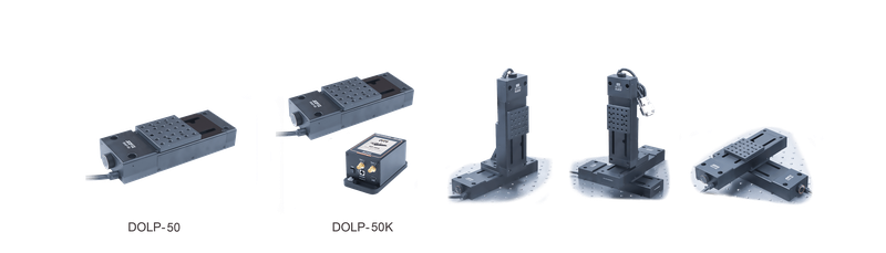
Stepper Motor Linear Translation Stage DOLP-50K
JCOPTIX stepper stages have Jiangsu metrology-institute test certification/reports. Precise, compact, stable stages are 36 mm high for systems with axes above 36 mm. The 65 mm × 65 mm tops fit DML65 13mm manual stages, DMV65 Z stages, DMR-1 rotation stages, DMG65 goniometers, and other manual products. Precision Hall limits give accurate homing and prevent overdrive damage. Ground ballscrews provide smooth nearly silent motion; 1 mm lead and rigid low-friction transmission minimize deformation/delay. JCOPTIX controllers readily achieve 100 nm steps. Rear knobs permit manual adjustment when unpowered/disabled; re-enabling requires position recalibration. Stage chips store calibration files; DCP-201C provides calibrated axial accuracy ≤±5.0 µm and bidirectional repeatability ≤±4.0 μm. Because data reside in the stage, any DCP-201C achieves calibrated accuracy. Stepper linear stages, 65 mm × 65 mm tops. Models: DOLP-30, DOLP-50, DOLP-100. Tops 65 mm × 65 mm; XY/XZ/XYZ combinations; built-in M6 quick mounting; travels 30 mm, 50 mm, 100 mm. Compact stable DOLP stages have 4 built-in M6 screws at the base ends for table mounting. Two central built-in M6 screws accepting a 3 mm key and two Ø5 mm dowel holes form multiaxis assemblies. Two stages quickly form XY; optional DOLP-AP forms left-/right-handed Z. Tops 65 mm × 65 mm and travels 30 mm, 50 mm, 100 mm support horizontal load 5 kg or vertical 1 kg, maintaining maximum 25 mm/s under full horizontal load. Calibration chips with DCP-201C provide axial accuracy ≤±5.0 µm and bidirectional repeatability ≤±4.0 μm; any DCP-201C preserves calibrated accuracy. Stepper linear-stage kits, 65 mm × 65 mm tops. Models: DOLP-30K, DOLP-50K, DOLP-100K. Controller/power included; tops 65 mm × 65 mm; XY/XZ/XYZ assemblies; built-in M6 screws; travels 30 mm, 50 mm, 100 mm. JCOPTIX kits match DCP-201C, including a stage, DCP-201C, standard 24V supply, and USB Type-C cable, needing no extra cable/power. Multiaxis stepper kits, 65 mm × 65 mm tops. Models: DOLP-30XYK, DOLP-30XZK, DOLP-30XYZK, DOLP-50XYK, DOLP-50XZK, DOLP-50XYZK, DOLP-100XYK, DOLP-100XZK, DOLP-100XYZK. XY/XZ/XYZ choices; controller/power; tops 65 mm×65 mm; built-in M6 quick mounting; M6 top holes for optics. All required assembly accessories are included; users quickly assemble chosen configurations without extras. Watch the video for first installation. Z adapter. Model: DOLP-AP. Builds Z from DOLP-30, 50, 100 series; user left/right assembly; supplied dowels/screws. It fits 3 stages, DOLP-30, DOLP-50, DOLP-100. Insert 2 Ø5 mm dowels under the stage, invert its axial orientation, and keep its lower end flush with the adapter bottom. Align one of two dowel-hole pairs, press together, then tighten two central built-in M6 screws with a 3 mm key. The horizontal center's 2 M6 countersinks mount Z to a table; 4 edge M6 countersinks and 2 Ø5 mm dowels combine with stages into left-/right-handed XZ/XYZ. Controller technical section, DCP-201C. JCOPTIX touchscreen stepper controller DCP-201C has a 2.8-inch color touchscreen and communications/power HUB ports. It drives JCOPTIX stepper optomechanics including linear, vertical, and rotary stages, filter wheels, shutters, and actuators, with 51200 microsteps/revolution. External signals trigger stage motion, or motion generates output triggers for other equipment. It suits on-site control and integration. A mounting plate secures it to optical tables; power supply and USB Type-C cable are included for PC software connection. New PC software supports multiple controllers with independent subwindows for centralized visual management. Built-in sequence control enables coordinated multiaxis motion without further development. Multilingual development interfaces support automated experiments and customization. New JMoition motion-control software supports DCP-201C and multiple stage types. Multiple controllers connect simultaneously, each with its own control/status subwindow. JMotion has built-in sequence editing to configure steps and execute them continuously in order, enabling complex automated motion without further development and making multidevice operation intuitive and efficient for automated experiments and customization. Core-parameter test methods: equipment specifications and DOLL examples, not measured specifications of this model. Stage core parameters. In precision manufacturing, semiconductors, optoelectronic inspection, and research, motion accuracy, stability, and reliability determine quality/efficiency. Test methods/standards define device quality; pitch, yaw, positioning accuracy, and repeatability quantify motion errors. Jiangsu metrology results: JCOPTIX commissioned the Jiangsu Institute of Metrology to test/report stage parameters under 1251-2010, Calibration Specification for Coordinate Positioning Measurement Systems. API XD Laser 6D interferometry measures positioning, pitch/yaw, and other parameters in one setup at 0.5ppm accuracy. Figure 1. Jiangsu institute's stage test report. JCOPTIX test methods: GB/T 11336-2004 procedures use Renishaw XL-80 interferometers and Nuoxu NORMAT1210 precision photoelectric autocollimators. Nuoxu NORMAT1210 measures pitch/yaw over ±1000 arcsec with ±1 arcsec accuracy and 0.2 arcsec repeatability, capturing tiny angular deviations/wobble across a 3800 arcsec × 2800 arcsec field. Segmented measurements and accumulated calculations determine actual-versus-ideal trajectory deviations. Optical accumulation improves accuracy; software directly outputs angles, usually arcseconds or microradians, with lower overall error. 1. Pitch/yaw. (1). Pitch: tabletop rotation θX about the horizontal X axis perpendicular to travel. (2). Yaw: θZ about the vertical Z axis. Figure 2. Pitch/yaw test schematic. 2. Repeatability/positioning accuracy. (1). Positioning accuracy is maximum error from the reference origin to target points over full travel, a key performance indicator. (2). Repeatability usually refers to repeated bidirectional positioning, such as ±X, and actual-versus-set position error over repeated arrivals at one command position, reflecting stability/consistency. Under GB/T 17421.2-2023, JCOPTIX uses Germany's Renishaw XL-80 with multiple target points and repeated forward/reverse arrivals. Actual positions and maximum deviations at each target calculate both repeatability and positioning accuracy. Accuracy is ±0.5 ppm, resolution 1 nm, and stable operation 0-40℃. Environmental compensation corrects temperature, pressure, and humidity, while up to 50 kHz dynamic acquisition captures small motion errors. Figure 3. Interferometric positioning test of precision direct-drive stages. 3. Speed stability. Actual speed fluctuation at a set speed reflects smoothness of control. Renishaw XL-80 dynamic acquisition at 50 kHz records displacement/time during commanded constant-speed travel; software derives speed/fluctuation. For example, JCOPTIX DOLL products over 50~200 mm travel reach 500 mm/s maximum and unloaded acceleration 15 m/s². 4. Homing accuracy. Deviation between the returned and original zero after motion reflects origin stability. Renishaw XL-80 records the initial zero and actual zero after repeated full-travel cycles; maximum deviation is homing accuracy. 5. Minimum achievable and repeatable increments. (1). Minimum achievable increment characterizes the smallest motion step. Renishaw XL-80 measures each actual increment during repeated commanded minimum steps to confirm the achievable minimum. (2). Minimum repeatable increment is the smallest physical step with stable repeatable response, statistically verified and normally no smaller than design resolution. Under GB/T 17421.2-2023, select a random 40 μm segment within full travel, step at the proposed minimum, for example 4 μm, use a 5 μm jump, and repeat 5 cycles. Measured repeatability must be below 20% of the increment, for example 4 μm × 20% = 0.8 μm. Every JCOPTIX motorized stage is tested to relevant standards before delivery and includes a shipment test report.
 Save to Favorites
Overview
Specifications
| Parameter | Value |
|---|---|
| Motor type | Two-Phase Bipolar Stepper Motor |
| Pitch | 600 µrad |
| Yaw | 900 µrad |
| Maximum Speed | 25 mm/s |
| Maximum Acceleration | 25 mm/s² |
| Repeatability | ± 2 μm |
| Platform Dimensions | 65 mm × 65 mm |
| Height | 36 mm |
| Body Material | 6061-T6 |
| Surface Treatment | Black Anodized |
| Horizontal Load | 5 kg |
| Vertical load | 1 kg |
| Axial Positioning Accuracy (After Calibration) [After calibration] | ± 5 μm |
| Axial Positioning Accuracy | ± 10 μm |
| Minimum Achievable Increment | 100 nm |
| Homing Accuracy | ± 1.5 μm |
| Return Error | 2 μm |
| Minimum Repeatable Increment | 4 μm |
| Velocity Stability | ± 0.5 mm/s |
| Platform Tapped Holes | 23 M6 Tapped Holes |
| External Profile Dimensions | 188 mm × 69 mm × 36 mm |
| Mounting Screws | Built-In M6 Screw |
| Included Controller Model | DCP-201C |
| Travel | 50 mm |
| Translation Stage Weight | 0.8 kg |
Key Features
Datasheet
Please provide your email to download the datasheet.
Invalid email format. Please try again.
Supplier Information
Related Products
-
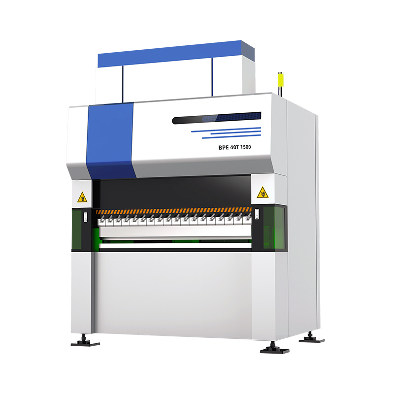 Electric Servo CNC Press Brake Machine 15T650
Motors and Drives
Auroralaser
Bending Capacity: 150 kN Bending Length: 650 mm Distance Between Columns: 300 mm
The Electric Servo Press Brake utilizes a fully electric servo drive system for zero standby consumption and rapid response. It delivers high-precision bending with quiet operation, significantly improving energy efficiency and productivity.
-
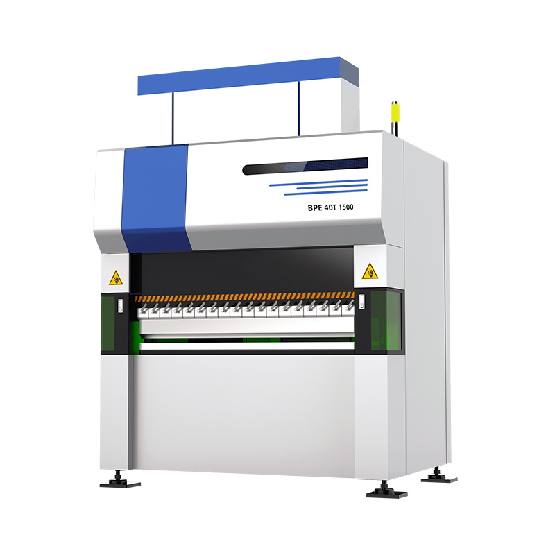 Electric Servo CNC Press Brake Machine 30T1050
Motors and Drives
Auroralaser
Bending Capacity: 300 kN Bending Length: 1050 mm Distance Between Columns: 800 mm
The Electric Servo Press Brake utilizes a fully electric servo drive system for zero standby consumption and rapid response. It delivers high-precision bending with quiet operation, significantly improving energy efficiency and productivity.
-
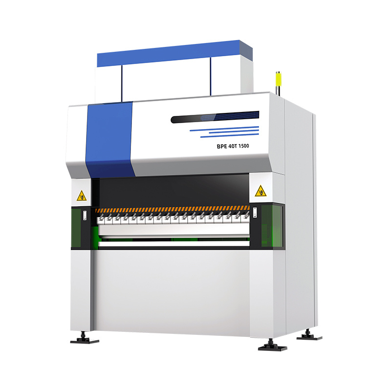 Electric Servo CNC Press Brake Machine 40T1500
Motors and Drives
Auroralaser
Bending Capacity: 400 kN Bending Length: 1500 mm Distance Between Columns: 1200 mm
The Electric Servo Press Brake utilizes a fully electric servo drive system for zero standby consumption and rapid response. It delivers high-precision bending with quiet operation, significantly improving energy efficiency and productivity.
-
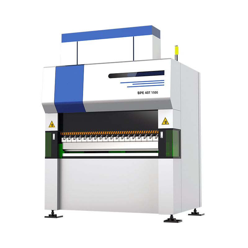 Electric Servo CNC Press Brake Machine 60T1500
Motors and Drives
Auroralaser
Bending Capacity: 600 kN Bending Length: 1500 mm Distance Between Columns: 1200 mm
The Electric Servo Press Brake utilizes a fully electric servo drive system for zero standby consumption and rapid response. It delivers high-precision bending with quiet operation, significantly improving energy efficiency and productivity.
-
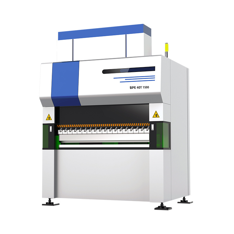 Electric Servo CNC Press Brake Machine 60T2000
Motors and Drives
Auroralaser
Bending Capacity: 600 kN Bending Length: 1500 mm Distance Between Columns: 1200 mm
The Electric Servo Press Brake utilizes a fully electric servo drive system for zero standby consumption and rapid response. It delivers high-precision bending with quiet operation, significantly improving energy efficiency and productivity.
Related Articles
Against the evolving demands for military‑grade hardware, rail transit equipment and heavy‑duty machinery that run under high‑shock vibrating conditions, anti‑loose connectors serve as indispensable hardware for stable power delivery and high‑speed signal transmission.
Developed by RealLight (Beijing), the R7M high‑power diode laser module belongs to the AW multi‑functional laser product family.
GYOPTICS 30 W collimated isolator is a highly‑reliable passive optical component optimized for 1064 nm high‑power laser systems. Characterized by low insertion loss and superior backward‑light suppression capability, it effectively blocks reflected light traveling back toward the laser resonator, eliminating back‑reflection‑induced instability and protecting fiber or solid‑state laser sources during long‑term operation.
Santec introduces the HSL‑20‑C‑E swept laser. Built on proprietary MEMS technology, this compact integrated light source combines high‑speed scanning and long coherence length, optimized for SS‑OCT imaging systems. Configurable start trigger and k‑clock outputs are available to meet development requirements for medical‑biological imaging and industrial non‑destructive inspection equipment.
Loading...
Name
Phone
Organization
Use Case

Database Platform