
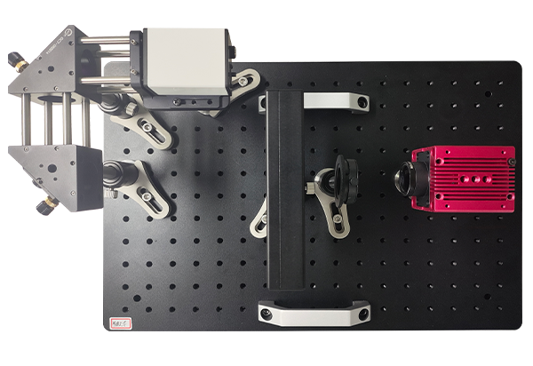
Physical Optics Experiment System
Digitally simulated optical elements produce the same theoretical phenomena as physical optics when loaded into the beam path, verifying optical calculations and formulas. Computer simulation combines theory with physical observation. Physical-optics teaching includes mask simulations of single slits, double slits, gratings and pinholes. This system uses amplitude control in a liquid-crystal spatial light modulator to simulate basic optical masks dynamically for different experiments: 1. Observe diffraction from different shapes. 2. Understand diffraction conditions and basic laws. 3. Understand conditions for stable interference. 4. Observe monochromatic double-slit fringes. 5. Measure fringe spacing and analyze its determining factors. 6. Compare multiple-slit and single-slit diffraction and measure intensity distributions to deepen understanding.
 Save to Favorites
Overview
Specifications
| Parameter | Value |
|---|---|
| Laser - Wavelength | 520nm |
| 45° Mirror Mount-Bottom Mounting Hole | M4 or M6 Threaded hole |
| 45° Mirror Mount-Clampable Diameter ΦD | Φ25.4mm |
| Mirror-Diameter φ | 25.4mm |
| Mirror-Focal Length f' | 100mm |
| Polarizer Mount-Clamping Dimensions | Ø25.4mm |
| Polarizer Mount-Clear Aperture | Ø22mm |
| Polarizer - Diameter | Φ25.4mm |
| Polarizer - Clear Aperture | 22.0mm |
| Polarizer - Extinction ratio | 500:1 |
| Beam Quality Analyzer-Pixel Size [Optional] | 3.45 μm × 3.45 μm |
| Beam Quality Analyzer-Active Area [Optional] | 14mmW×10mmH |
| Beam Quality Analyzer-Resolution [Optional] | 4096 × 3000 pixels |
Datasheet
Supplier Information
Related Products
-
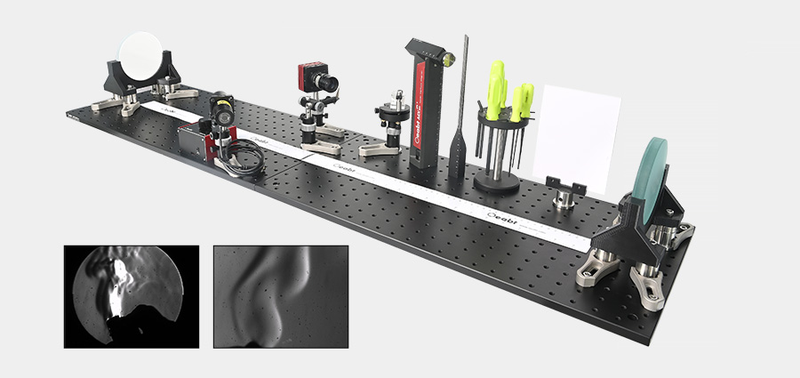 OEDU-GSME Schlieren Experiment Demonstration Kit
Research & Education
Oeabt
Using the knife-edge method, the system converts light-ray deflection into intensity changes. Lower-density regions, such as hot airflow, deflect rays in a particular direction and form brighter spots at the knife edge; higher-density regions form darker spots. The camera thus records an image representing the density distribution.
-
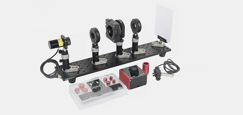 OEDU-PLE Light Polarization Experiment
Research & Education
Oeabt
Light polarization experiments investigate polarization properties and behavior in different media and optical devices, demonstrating polarization phenomena and their applications in science and technology.
-
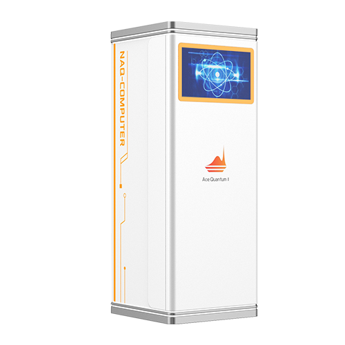 Neutral-Atom Quantum Computing System and Submodules
Research & Education
Acephoton
The company has developed a neutral-atom quantum computing system and submodules to provide a full-stack quantum computing solution from core devices to complete-system architecture. Based on advanced neutral-atom technology, it integrates atom trapping, optical-tweezer arrays, quantum-state manipulation and readout. A flexible modular architecture allows core submodules to run independently for individual technology verification or connect seamlessly for coordinated operation, simplifying assembly, upgrades and maintenance. Serving university research, algorithm development and commercialization exploration, these highly stable, scalable system-level products lower R&D barriers and accelerate deployment and scale-up of neutral-atom quantum computing.
-
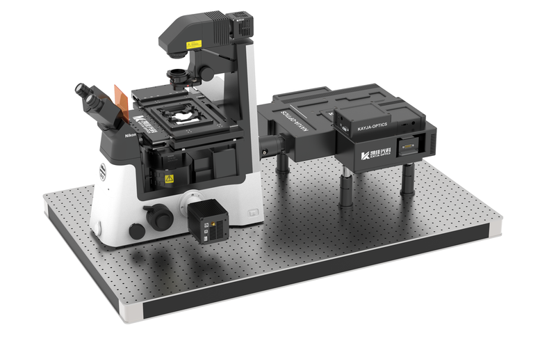 Holographic Optical Tweezers Configuration Parameters
Research & Education
Kayjaopt
Configuration Parameters-Holographic Optical Tweezers Module: 1) Generates ≥100 optical traps simultaneously for particles of 1-50μm. 2) Spatial phase modulation 0-2π, response band 1000-1100nm, light utilization ≥97% (@1064nm), 1272*1024 pixels, pixel size 12.5μm and effective area 15.9mm*12.8mm; select the SLM response band to match the laser wavelength. 3) Dynamically adjustable trapping force. 4) Supports Fresnel, cylindrical and conical lenses, gratings, Laguerre-Gaussian beams, combinations and custom 3D manipulation. 5) A 1064nm laser, with other wavelengths optional, power ≥3W, beam quality M2 of 1.2, modulation frequency 10khz and a laser cooling module. 6) Force measurement accuracy 0.5pN. Configuration Parameters-Single-Trap Independent Control Module: 1) Includes a single high-power 1W 1064nm laser, with other wavelengths optional. A galvanometer scanner enables high-speed two-dimensional movement of a single optical trap, complementing the SLM in high-speed applications. Supports independent planar path planning and strong single-point trapping. 2) Includes a data acquisition card. Configuration Parameters-Microscope Main Body: 1) Nikon Ti2-U inverted microscope as standard; adapters and optical-path interfaces can also suit an existing laboratory microscope. 2) A 100X oil-immersion objective or 60X water-immersion objective dedicated to optical tweezers.
Holographic optical tweezers use mechanical light-matter interactions for precise three-dimensional microscopic manipulation and force analysis. A suitably distributed beam generates piconewton forces that trap and move viruses, bacteria, organelles, cells, micro/nanoscale transparent or metallic particles and micro/nanomotors without mechanical damage. Light penetration also enables manipulation of internal components without damaging particle surfaces. Noncontact operation, low damage, diverse targets and precise displacement/force measurement have led to use in life sciences, physical chemistry and aerosol science, with potential in micro/nanofabrication and sensing. Optical tweezers are essential for biophysical/biomechanical characterization; inventor ASHKIN received the 2018 Nobel Prize in Physics for their biological success. Near-infrared wavelengths, commonly 1064nm, are essentially nondestructive to biological specimens. Forces range from femtonewtons (10⁻¹⁵N) to hundreds of piconewtons (10⁻¹⁰N), matching microscopic biological forces. HoloGraphic Optical Tweezers (HOT) revolutionized optical trapping. Kaijia Photonics' SLM-HOT uses a liquid-crystal phase-only spatial light modulator (SLM; Spatial Light Molator) as a holographic element. Wavefront phase shaping generates trap arrays. Computer-loaded and switched holograms position traps; preset patterns simultaneously trap and manipulate multiple particles in 3D, with independent dynamic control of any array particle. New trap types rotate, transport and sort particles. Phase modulation can be added to one or more traps to generate special focal fields such as Bessel and vortex beams. K-Well commercial operating software sets laser power and camera parameters, generates/manipulates traps and arrays, plans straight/circular/rectangular/custom paths, provides multiple force-measurement methods, real-time mechanical analysis/display and holographic phase projection. K-BeamGenerator, developed for the company's tweezers, generates phase holograms for different SLM configurations. Modules: beam shaping with Laguerre, Airy and Hermite beams; diffractive optics including cosine/blazed gratings, axicons, cylindrical and Fresnel lenses; 3D point arrays with multiple positions and corresponding phase maps; custom grating/beam and grating/lens combinations.
-
 Laser-Scanning Optical Manipulation System
Research & Education
Kayjaopt
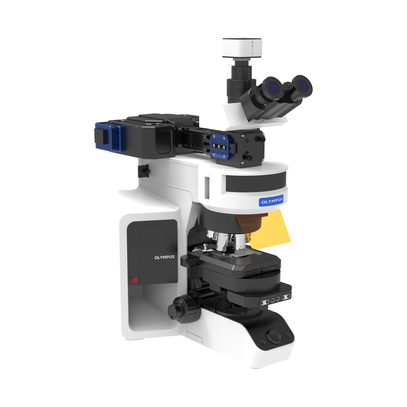
Controls focused-laser 2D scanning under a microscope with programmable scan paths. Galvanometer elements scan incident lasers from visible to near-infrared wavelengths in two dimensions, providing temporal scanning of specified spatial light-field structures. Suitable for single-photon and two-photon absorption experiments.
Related Articles
Recently, our R&D crew carried‑out performance tests on domestically‑made third‑party LiDAR hardware. The original built‑in sensor chip was replaced by Optics‑Valley Quantum’s new‑generation D‑XXLA200‑02 chip.
Founded in 2019, Jilin JC Ultrafast Equipment Co., Ltd. is a high-tech enterprise incubated by the Ultrafast Optoelectronics Center of Jilin University. Our R&D team owns 15 years of profound experience in femtosecond laser micro-nano fabrication.
An infrared transmitter (IR transmitter) is a basic electronic component that sends invisible infrared light signals for short-range wireless control. It is widely used in daily electronics, smart home devices, and industrial equipment due to its low cost, low power consumption, and stable performance.
As a top‑tier supplier of tunable laser chips, Shandong Zhongxin Optoelectronics Technology Company has newly launched the world’s first budget‑friendly fiber‑Bragg‑grating (FBG) demodulator and scanning module.
Loading...
Name
Phone
Organization
Use Case

Database Platform